This document was prepared by a National Network of Environmental Management Studies grantee under a fellowship from the U.S. Environmental Protection Agency. This report was not subject to EPA peer review or technical review. The U.S. EPA makes no warranties, expressed or implied, including without limitation, warranty for completeness, accuracy, or usefulness of the information, warranties as to the merchantability, or fitness for a particular purpose. Moreover, the listing of any technology, corporation, company, person, or facility in this report does not constitute endorsement, approval, or recommendation by the U.S. EPA.
Identifying leaks in landfill liners is an essential part of waste management. EPA’s Technology Innovation Office (TIO) provided a grant through the National Network for Environmental Management Studies (NNEMS) to prepare a technology assessment report on identifying leaks in landfill liners. This report was prepared by a senior undergraduate student from Virginia Tech during the summer of 1998. It has been reproduced to help provide federal agencies, states, consulting engineering firms, private industries, and technology developers with information on the current status of this technology.
About the National Network for Environmental Management Studies (NNEMS)
NNEMS is a comprehensive fellowship program managed by the Environmental Education Division of EPA. The purpose of the NNEMS Program is to provide students with practical research opportunities and experiences.
Each participating headquarters or regional office develops and sponsors projects for student research. The projects are narrow in scope to allow the student to complete the research by working full-time during the summer or part-time during the school year. Research fellowships are available in Environmental Policy, Regulations, and Law; Environmental Management and Administration; Environmental Science; Public Relations and Communications; and Computer Programming and Development.
NNEMS fellows receive a stipend determined by the student’s level of education and the duration of the research project. Fellowships are offered to undergraduate and graduate students. Students must meet certain eligibility criteria.
This report is intended to provide a basic summary and current detection of leaks in landfill liners. It contains information gathered from a range of currently available sources, including project documents, reports, periodicals, Internet searches, and personal communication with involved parties. No attempts were made to independently confirm the resources used.
Identifying leaks in landfill liners is an essential part of waste management. Several types of leak detection tools can be installed in addition to monitoring wells to identify leaks soon after they occur. This paper provides an overview of some tools for vadose zone monitoring, as well as the advantages, disadvantages, and costs associated with them.
Federal law requires all landfills to include a leak detection system above the bottom composite liner. The system must consist of a layer of granular drainage materials with a slope of at least one percent, so any leachate which passes through the top liner will drain into the sump at the bottom of the unit, where its volume is recorded.(40 CFR 264.301) This system establishes what volume of leachate has leaked through the top liner, but it does not indicate whether or not leachate is leaking through the bottom liner.
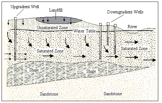
In addition, all landfills are required to install a groundwater monitoring system. The system must consist of both up gradient and down gradient wells which allow sampling of the groundwater in the uppermost aquifer, as shown in figure 1. The number, spacing, and depths of the required wells are dependant on the geologic and hydrologic properties of the area. (40 CFR 258.51)

By collecting groundwater samples and analyzing them, landfill operators can usually detect contaminant plumes caused by leaks in the landfill liner. One limitation of this method is that it does not prevent the groundwater from becoming contaminated. Another limitation is the expense of comprehensive monitoring for all groundwater which comes in contact with a landfill. Because most landfills are lined with geomembranes, most leaks are point sources, not widespread. If there is no monitoring well in the path of a plume, it is possible for the front of the plume to pass by the line of wells at the point of compliance without being detected. Installing enough monitoring wells to be sure of intercepting a narrow plume in any position can be prohibitively expensive. (Godfrey, 1987)
California has especially rigorous monitoring requirements. State law requires testing for leakage in the vadose zone under waste disposal sites. (CA Code) The two most common ways to comply with this requirement are lysimeters, which collect pore water for later removal and testing, and soil core sampling. Both of these methods require laboratory testing and neither can easily pinpoint the location of the leak. (Daniel, 1987)
In addition to the monitoring methods required by law, some landfill owners are choosing to install systems of leak detection sensors. These sensors permit early leak detection without laboratory analysis, and often locate the leak.
Several different types of sensors provide these benefits. Some work by electrical methods, measuring the resistivity or dielectric constant of the soil. Others work by chemical methods, either analyzing soil vapor or reacting directly to leachate. These sensors are often dependant on the composition of the leachate. Still others use tracer chemicals to detect leaks. Use of these technologies is not widespread, mainly because of cost. Most must be installed during construction and are not applicable to existing landfills.
Each of the leak detection systems available has different advantages and disadvantages. The perfect vadose zone monitoring system has not yet been designed, but the ideal system would:
Research on new sensors for leak detection at landfills is ongoing, but it is also limited because the market for this optional extra level of detection is extremely small.
The main reason leak detection sensors are not more widely used at landfills is the cost. By law, sensors may only be used in addition to monitoring wells, not in place of them. Therefore, it is uncommon for a landfill owner to choose to install leak detection sensors. The owner has no way of knowing whether or not a major leak will ever occur, so the benefits of detecting a hypothetical future leak earlier do not outweigh the immediate costs of installing a vadose zone leak detection system.
A comparison compiled by Inyang (Rumer, 1995) of monitoring costs for a hypothetical landfill showed that sensors can be less expensive than monitoring wells. Inyang compared the cost of monitoring a 20,000 ft2 area for 20 years with monitoring wells to the cost of monitoring the same area with the Raychem system for electro-chemical monitoring. (see section 2.5 d) The costs are broken down in the following table:
|
Cost comparison for monitoring wells vs. electro-chemical sensing |
|||
|
Monitoring technique |
Unit cost ($) |
Number required |
Total item cost |
|---|---|---|---|
|
Groundwater monitoring wells
|
5,000 18,000 per well 100,000 |
3 3 - |
15,000 54,000 100,000 |
|
Total cost |
169,000 |
||
|
Electro-chemical sensing
|
5,000 1,200 300 400 120,000 |
1 3 3 3 - |
5,000 3,600 900 1,200 120,000 |
|
Total cost |
130,700 |
(Rumer, 1995)
Although the cost of the electro-chemical system is lower than that of the monitoring wells, the entire system would cost $299,700, which is substantially more than the wells alone.
This report includes information on permanently emplaced monitoring systems which detect leaks in the vadose zone. Surface geophysical techniques such as ground penetrating radar will not be covered; nor will direct push site characterization techniques or sampling techniques such as lysimeters.
Most of the techniques used for locating leaks in subsurface barriers are not readily applicable to landfills. For more information on ground penetrating radar, electrical resistance tomography, and other subsurface barrier monitoring techniques, refer to the following report--
Rumer, R.R. and J.K. Mitchell, eds. 1996, "Assessment of Barrier Containment Technologies: A Comprehensive Treatment for Environmental Remedial Application." Product of the International Containment Technology Workshop. National Technical Information Service, PB96-180583.
There are two main ways of detecting leaks using electrical methods: the two electrode method and the electrode grid method. Both leak detection techniques utilize the insulative properties of geomembrane liners. The first method detects the flow of current from one electrode to another through a hole in the insulative liner. The second method depends upon the liner to insulate the containment area so that only leachate which has escaped into the soil will be detected.
The first method requires installing one electrode inside the landfill, and another in the ground outside the containment area. Electrical current is introduced into the containment area by the electrode inside the landfill. Because of the electrical resistance of the liner, the current will not flow to the electrode in the ground if there are no holes in the liner. Flow of current from one electrode to the other indicates a leak, as shown in figure 2. (White et al, 1997)
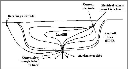
The two electrode method can be especially useful for detecting leaks in pre-existing landfills because this technique does not require the installation of any sensors below the liner.
This method indicates only the existence of a leak, not the number, size or location. Current flow can be caused by one leak or several, and by large or small leaks. In order to determine the location of the leak, a map of the voltage distribution must be determined. This is achieved by passing voltmeters systematically over the liner within several inches of the surface. An area of high voltage indicates a leak. Because voltmeters cannot be passed directly over the liner if the landfill has begun accepting solid waste, the two electrode method is popular for use in liquid containment basins and on solid waste disposal cells which have not yet begun accepting waste. (Laine et al, 1993)
Sandy Lane Landfill is located on a major aquifer in the United Kingdom and within one kilometer of a public well. The site was originally a sandstone quarry. In order to receive permission to begin planning and construction, its designers decided to include an electrical monitoring system in the plans.
The system included a combination of the electrode grid method which will be discussed in section 2.1.2 and a version of the two electrode method. Instead of a single electrode being placed outside the liner, a grid of electrodes was installed below the liner to allow leak location. A single electrode was installed in the sand protection layer above the liner as the current source for liner integrity testing. If the electrode grid below the liner detects current from the electrode inside, it indicates that a breach has occurred in the liner. (White et al, 1997) For more information on the electrode grid, see section 2.1.2 c.
The second method makes it possible to actually locate leaks in active and closed solid waste landfills. It requires installing a grid of electrodes beneath the primary liner during construction. The electrodes are used to energize the area around the liner and to measure the resulting voltage of the soil near each electrode. Because leachate has a higher electrical conductivity than either soil or water, an area of a difference in voltage indicates that leachate has escaped from the liner at that location.
This system involves simple, durable components that can last for several decades. It monitors the entire area below the liner, not just certain points. In addition to detecting leachate releases, the electrode grid can also detect holes in the liner before waste is placed in the cell in the manner described above in section 2.1. Current is introduced into the protective soil layer. If the current is detected by the electrodes, it has passed through a hole in the insulative geomembrane liner.
This system is not applicable to existing landfills because the electrodes must be installed during the construction of the cell.
Sandy Lane landfill, which was introduced in section 2.1.1 c, can also detect leaks by the electrode grid method. The monitoring system was installed when the landfill was built in 1995. The lower liner is underlain by a grid of stainless steel monitoring electrodes spaced 20 meters apart, as shown in figure 3. This distance was chosen based on mathematical modeling and small-scale testing. Multicore cables connect the electrodes to each other and to the control equipment, which is housed in the weigh station. The area around the electrodes was backfilled with bentonite enhanced sand because of its high conductivity.
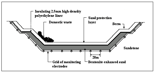
The system was first used to verify the continuity of the liner after it was installed. One intentional and one unintentional hole were located and repaired. During the first year of operation, monitoring was conducted monthly. Data collection typically took one to two hours. All voltage irregularities were found to correspond to holes in the geomembrane. After the first year, monitoring was conducted according to a schedule based upon past data.
In the event of significant contamination of the area below the landfill, the monitoring system can be used to map the pollution plume as it moves toward the monitoring wells, both in the vadose zone and in the groundwater. Initially, the system was installed over an area of 30,000 meters. The system is being installed in other cells as they are constructed. (White et al, 1997)
d. Example 2-WESTEC’s Electronic Leak Detection System
The Electronic Leak Detection System produced by Westec, Inc. consists of an exterior patch panel installed during the construction of the liner system. Electrical nodes are connected to the panel in a grid with 100 feet of space between nodes.
The system can detect leaks as small as 50 gallons. It runs on 12 volt batteries. After the installation of the system, it must be calibrated by introducing a controlled amount of simulated leachate below the liner and monitoring the subgrade response. (VendorFACTS, 1997)
Analysis of a positive reading reveals the size of a leak, in addition to its existence and location. Computer processing of the data produces a three dimensional graphic image of the leak. The cost of the system is typically less than a third of the cost of the geosynthetic liner. (Robison, 1996)
The system has been installed in over 20 million square feet of containment facilities at ten sites in the western United States since its first installation in 1987. In 1995, the system was installed at a landfill in Italy. (VendorFACTS, 1997) The largest installation of this technology has been operating at a gold mine in Elko, Nevada for eleven years. (Robison, 1996)
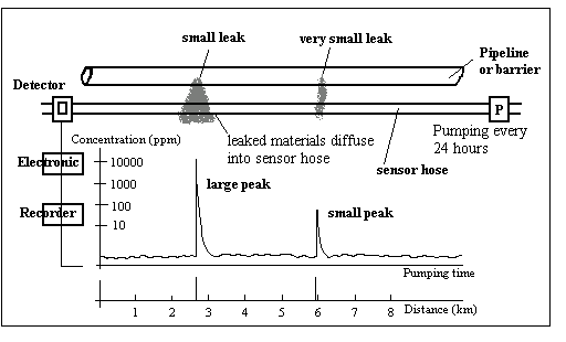
Diffusion hoses were originally developed for detecting leaks in pipes. A diffusion hose system consists of a network of vapor-permeable tubes emplaced in the ground under the landfill. After a set period of time, the gas in the hose is pumped out through a detector which records contaminant concentration as a function of pumping time, as shown in figure 4. By observing the time at which contaminants were detected, the leak location can be determined within one or two meters. Because the vapors of a leak diffuse into the tube at a concentration proportional to the concentration in the soil, the approximate leak size can be determined by analyzing the vapor concentration inside the tube. The identification of the composition of the leak is possible by sampling the contaminated gas as it passes out of the detector and analyzing it by gas chromatography or other laboratory methods. (Stammler, 1985)
Diffusion hoses are widely available for tank and pipeline use. The system is automatic, so it is not necessary for a technician to spend time running tests. This autonomy reduces the cost of operation.
In order to be detected by the diffusion hose system quickly, the leachate must produce vapor. If the leachate does not produce any vapor, the system will not detect the leak until the leachate comes directly into contact with the hose and the liquid itself diffuses into the tube. If the leachate produces no vapor, the diffusion hoses must be placed very close together to produce a high probability of intercepting a leak at any point in the liner. This would increase the cost significantly.
The hose of the LEOS leak detection system, manufactured by Siemens, is composed of several layers of durable plastic. The tube is filled with purified air, which is later evacuated and tested for contamination with semiconductor gas sensors. When the alarm threshold is crossed, the location and concentration distribution of the leak are displayed. Leaks can be located to an accuracy of 0.5% of the length of the hose. ( LEOS Leak Detection System page)
Capacitance sensors measure the soil’s dielectric constant, which is a measure of how well the soil resists a change in the electric field. The dielectric constant of dry soil is around 5 and the dielectric constant of water is around 80. When soil becomes moistened by a leak, its dielectric constant increases. Measuring the change in dielectric constant of an area over time can indicate whether or not a leak has occurred there.
The sensors work by frequency domain technology, which means they resonate at a harmonic frequency dependent on the dielectric constant of the soil around the probe. From the frequency, the moisture content can be determined with the calibration curve. (VendorFACTS, 1997) Capacitance sensors are commonly used in agriculture to determine irrigation schedules.
Capacitance sensors are readily available for purchase, as several companies market them for agricultural use. They can be programmed to take moisture readings automatically.
Moisture content is the only quantity measured by capacitance sensors, so they measure all moisture, not specifically leachate. They must be installed far enough above the highest water table to be sure the probe doesn’t detect groundwater. Each probe only measures the dielectric constant of the soil immediately surrounding it, so the more complete the leak detection coverage desired, the more probes are necessary, and the more the system will cost. The probes must be buried during construction of the landfill.
c. Example- Troxler’s Sentry 200 EMMS
The Sentry 200 Environmental Moisture Monitor System is produced by Troxler Electronic Laboratories. The system consists of a central unit, the ProbeReader Plus, and up to eight probes which can be connected to the reader by coaxial cable. The ProbeReader must be connected to a data logging system for information retrieval. Each probe costs $1,000 and each ProbeReader costs $4,700. The system is capable of taking measurements either continuously or at regular intervals. It can run on either 12 volt batteries, which last four hours, or AC electrical current.
Each probe measures the dielectric constant of the approximately 1.5 liters of soil surrounding it. The probes should be kept 12 inches away from metal structures. (Vendor FACTS, 1997) The probes are 12 inches long and two inches in diameter, as shown in figure 5. They weigh eight pounds apiece. The outside of the probe is made of stainless steel, high density polypropylene, and fiberglass epoxy laminant, making the probe resistant to corrosion and breakage. (Troxler Sentry 200 Environmental Moisture Monitor Page)
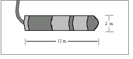
In April of 1995, the Sentry 200 EMMS was installed at San Marcos Landfill in San Diego, California. Sixty probes and eight ProbeReader Plus units were installed. The total cost of the project was $219,000, including equipment, engineering, and installation costs. The system automatically measured moisture levels four times per day, and a person collected and examined the data every two weeks. (VendorFACTS, 1997)
Using tracers as a method of leak detection originated for use in storage tanks and pipelines, but tracers can be used to detect leaks in any type of containment facility, including landfills. Sample collection probes must be inserted in the ground around the perimeter of the landfill. To test for leaks, a volatile chemical tracer is injected into the landfill. If the tracer is detected at the sampling points, a leak exists.
The composition of the leachate is unimportant, as the properties of the tracer are known. Tracer systems can be used on any type of containment facility. Also, tracers can be used to detect leaks at any stage in the life of the landfill because the probes are placed around the perimeter of the facility. The volatile tracer travels through the soil gas to the probe.
Most tracer systems do not usually find the location of the leak, they only determine whether or not leaks exist. In addition, many systems require soil gas samples to be manually collected and analyzed by a technician, which increases operations costs. Systems which automatically collect and analyze samples are rare.
c. Example- Tracer Research Corporation’s Automatic Leak Detector
Tracer Research Corporation provides leak detection services to its clients, which include Texaco Refining and Marketing and almost all US Air Force bases. They have applied their TracerTight systems not only to thousands of petroleum storage and transport facilities, but also to hazardous waste sewer systems and landfill liners. (VendorFACTS, 1997)
One of its products, the Automatic Leak Detector (ALD 2000), is an automated system capable of continuously collecting and analyzing samples for the presence of tracer and hydrocarbons in the soil. Sample data can be collected on a remote computer via a modem. (Tracer Research Corporation page)
The Tracer Research Corporation’s soil gas probes are five feet long and weigh two pounds each. The number of sampling probes necessary depends upon the size of the area to be monitored. The TracerTight system costs around $15,000. (VendorFACTS, 1997)
Electro-chemical sensing cables were originally designed for detecting leaks in storage tanks and pipelines. Most detect hydrocarbons, but the cables can also be made permeable to specific contaminants or to water. For example, Lawrence Livermore National Laboratory is developing a carbon tetrachloride-specific cable.
The target contaminant causes a physical or chemical change in the sensing cable. This change either initiates or interferes with electrical or optical signals. Many electrical cables detect leaks by measuring the drop in voltage in the cable caused by contact with contaminants. Most fiber optic cables operate by measuring either a change in the optical attenuation of the cable or the fluorescence of the contaminant when it comes in contact with an organic dye. Most of the reactions are reversible. Cables which utilize a reversible reaction do not need to be replaced after a leak occurs. (Rumer et al, 1995)
Chemical sensing cables are widely available, especially for detecting hydrocarbons. If the composition of the leachate which will be produced by a landfill is known, a sensing cable which is compatible to the leachate can be installed during construction.
The cables only detect a narrow range of contaminants. Each landfill must verify that a particular cable would detect the specific type of leachate that will be produced there. No company has developed a cable specifically tailored to detecting leachate. Further research is necessary to determine the extent of the applicability of sensing cables to landfills.
c. Example 1- Noverflow’s SMART CABLE
Noverflow Inc. is developing two types of fiber optic leak detection cables. Both detect organic corrosives and petroleum hydrocarbons. They are applicable to both industrial and municipal landfills.
Type I sensors are cut on contact with the contaminant because of swelling and degradation of the polymer coat. An optical time domain reflectometer sends a light pulse along the cable and measures the amount of time it takes to reflect back to determine the distance to the cut, and therefore the location of the leak. These cables can monitor distances of up to 50 miles.
Contaminants modify Type II sensors to change the refraction of light pulses traveling through the cable. A light emitting diode and a photo detector are used to detect the leak. This sensor is reversible unless enzymes have been incorporated into it to test for a specific chemical. This type of cable can only monitor distances of up to 100 feet because the cables are made of fibers with high optical attenuation.
Units can be configured to be powered by solar energy, eliminating the need for batteries or other power sources. The cables cost $2.00 per foot. This cost includes an optical time domain reflectometer. (VendorFACTS, 1997)
Raychem manufactures a wide variety of electrical leak detection cables. One detects water, another detects conductive liquids, another detects fuels, and still another detects organic solvents.
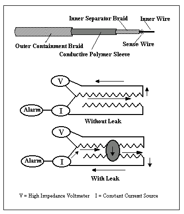
The cables all function on the same general principle. The cable contains two circuit loops, one of which carries a current and the other of which contains an alarm. When electrical contact is made between the two circuits, the alarm is tripped, as shown in figure 6. Contact is made in some cables by a conductive fluid which carries current from one circuit to the other. In others, electrical contact is made by direct wire contact. The conductive polymer sleeve which surrounds the inner sense cables expands on contact with the target contaminant. The outer containment braid forces the polymer to expand inward, squeezing the sense wires together. The location of the leak is then calculated automatically. (Raychem Leak Detection and Location page)
Venice Park Recycling and Disposal Facility in Lennon, Michigan has a system which makes it possible to locate leaks visually. Piping networks run along both the primary and secondary liners. Operators can send a camera into the piping system where a leak is suspected to locate where liquids are entering the pipe. (Dunson, 1996)
A system of placing electrically conducting wires inside geotextiles for use in leak detection has been patented by Koberling, a German company. When the wires come in contact with leachate, they short circuit, signifying a leak. The main limitation is that the wires, once shorted out, cannot easily be replaced. (Stammler, 1986)
3.1 Geosynthetic Membrane Monitoring System
The Sandia National Laboratories are currently developing geomembranes with embedded fiber optic sensors. Sensors were first incorporated into materials and structures for defense and space applications. These “smart” structures have been used to help monitor weapons tests, naval ships, and the space shuttle. (Borns, 1997) The Sandia labs are now applying the same strategy to environmental needs.
By incorporating fiber optics into geomembranes, the Sandia labs have produced a membrane which can be monitored for strain. This capability is especially useful for detecting stretching and tearing in geomembranes used as landfill liners and caps. Strain detection is possible because the fiber optic lines are crimped into small folds called microbends. The microbends are either distributed evenly along the entire optical fiber or the fiber may have short sections of microbends a few meters apart, as shown in figure 7. As the geomembrane tears or stretches, the microbends flatten out, changing the way optical signals are reflected through them. (Geosynthetic Membrane Monitoring Systems page)
Optical fibers can be incorporated into geomembranes in several ways. The sensors can be extruded along with the geomembrane during manufacture, or the factory can laminate, glue, or weld them on afterwards. The Sandia National Laboratories have determined hot shoe welding to be the most promising attachment technique. (Borns, 1997)
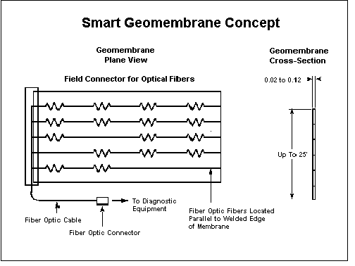
In addition to testing several different methods of attachment, the Sandia labs have also tested several different types of sensors: absorption-type, bragg grating, mircobend, and others. They expect the variety of possible combinations of sensor types and attachment methods to allow them the flexibility they need to meet the specific needs of individual sites. (Borns, 1997)
Field scale testing on the Geosynthetic Membrane Monitoring System was completed in October, 1997. For the test, a 43 x 4.5 m section of geomembrane was installed as a cap over a test facility which was designed to simulate both local and general subsidence. The strain in the membrane was measured for three months as water and air were drained from fabric bladders and intertubes in the test cell. The data provided by the sensors indicated the location and magnitude of the subsidence. (Borns, 1998)
Although the Department of Energy has discontinued funding the project, the Sandia labs are conducting ongoing research on optical fiber sensors for fluid level, leak detection and moisture content. (Borns, personal correspondence) Their goal is to keep the cost of incorporating sensors at or below 20% of the cost of the geomembrane. (Geosynthetic Membrane Monitoring Systems page)
Sandia National Laboratories are working together with Science and Engineering Associates, Inc. to develop SEAtrace, a leak detection system which uses gaseous tracers. SEAtrace is capable of determining the location, size, and start time of a leak by analyzing data with an inverse global optimization code. (Barrier Verification and Monitoring System page)
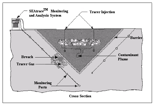
SEAtrace requires a multipoint monitoring system to be installed outside the liner, as shown in figure 8. Then a tracer gas (usually sulfur hexaflouride or carbon dioxide) is injected inside the containment area. If the gas reaches the monitoring ports, the amount of tracer in the soil gas at each monitoring point is measured over time. The global optimization code uses these parameters to find the best fit solution for the location, size, and duration of the leak.
The SEAtrace system has undergone proof-of-concept field testing in Technical Area 3 at Sandia National Laboratories. It was shown to be capable of locating a leak to within 0.5 meters and determining its size to within 0.2 meters. (Williams et al, 1997)
Flexible Liner Underground Technologies (FLUTe) have designed their version of an ideal landfill monitoring approach. The system consists of a layer of coarse materials underlain by a layer of fine materials and another layer of course materials. (sand-silt-gravel, for example). The fine layer widens the leak and must be capable of wicking leachate horizontally for 30 feet or more. Two tiers of perforated pipes connected to surface manifold pipes are installed inside the layers to collect vapor samples and to allow access for moisture sensors and logging tools, as shown in figure 9. Pipes made of a geologic material (such as vitrified clay) are recommended to allow electrical and radiation based monitoring devices to be used inside the pipes.
Routine monitoring is accomplished by drawing the pore vapor out of the system through a charcoal filter which can then be analyzed for contamination. The air is drawn out through the manifold which connects the upper tier of pipes. Fresh air is allowed in through the manifold which connects the lower layer of pipes. In this way, all the air in the pipes and the monitoring layers is drawn through the filter.
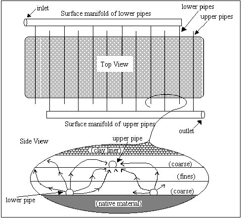
If contaminants are detected on the filter, the location and size of the leak can be determined by towing logging tools through the pipes. This is best accomplished by using SEAMIST, a versatile everting liner system which makes it possible to perform many monitoring tasks including transporting equipment safely inside a horizontal well. The leak can be directly sampled by using the SEAMIST system to wick pore liquid samples through the pipe. Because no instruments are permanently emplaced in the ground, new technologies can be used in the existing access system as they are developed.
Once the leak has been located, the FLUTe system can also be used to control the leak. One option is to control or heat the air flow in the system to dehydrate the leak and keep it from flowing. Other options are to freeze the leak or contain it by injecting a sealant into the upper coarse bed with tubing emplaced in the upper pipes. (Keller, 1995)
The estimated cost of installing the system is approximately $100,000 per acre in 20 acre increments. About 70% of the cost is for the installation of the layered bed materials. There are also lower cost options such as installing only one tier of piping. The SEAMIST canister costs about $7,000 and the liner costs $10 to $20 per foot.
Los Alamos National Laboratory is currently using a form of the FLUTe ideal design in passages beneath radiation waste pits in TA-54. The University of Texas is monitoring experimental cover designs with the SEAMIST system in horizontal passages in Hudspeth, Texas.
To monitor exiting landfills, horizontal wells can be drilled beneath the liner. FLUTe has developed a method of using an everting water driven liner to help drill horizontal wells which contain less mud than conventionally drilled wells. These wells can be used for towing logging instruments under the landfill and for wicking pore liquid samples with the SEAMIST system. (Keller, personal correspondence)
There is some interest in using Light Detection and Ranging as a leak detection technique. LIDAR is similar to RADAR, but instead of sending and receiving radio waves to determine distances by remote sensing, it uses light waves.
LIDAR is widely used to measure atmospheric conditions. It may also be possible to use it underground. If a horizontal perforated tube is installed down gradient of the landfill just above the water table, it may be possible to use LIDAR to detect the contaminant vapors which enter the tube. This system would not prevent groundwater contamination, but it would improve the probability of detecting a plume before it passes the point of compliance. This technique could be applied to both new and existing landfills.
One example of lasers currently being used for leak detection is Lasersonic, a system produced by Laser Imaging Systems. Sodium hexaflouride is placed inside the object to be tested as a tracer gas. When the Lasersonic is pointed at the object, any gas which has escaped into the air strongly absorbs the light energy of the laser, then releases it as sound energy. Lasersonic receives the sound energy and finds the location of the leak. (Laser Imaging Systems page)
As leachate flows through soil, it makes a slight noise. Fluids moving through coarse sand or gravel at 10 mm/s or more have been shown to produce a detectable level of sound. The sound waves below a landfill can be monitored by installing wave guides in a layer of coarse material beneath the liner and connecting them to geomicrophones. The wave guides are metal rods 10 to 20 mm in diameter and up to 100 m in length. If the wave guide has a geomicrophone at both ends, the location of the leak can be determined because the time the sound took to travel to both ends is known. (Stammler, 1985)
Acoustic methods are often used to detect gas leaks from pipes and valves. Non- Destructive Testing International, for example, markets the Computerized Leak Analyzer, which acoustically detects gas leaks, especially in boilers and steam-operated systems. (Clan page) Argonne National Research Facilities includes a laboratory specifically for research in this area called the “Acoustic Leak Detection Laboratory.” (Argonne National Laboratory page)
Palmer Environmental markets a liquid leak detector for underground pipes called the Corralog leak manager. The instrument uses two microphone sensors to listen to the noise produced by the leak, then locates the leak on the pipe by comparing the time taken by this noise to reach the two sensors at either end of the pipe section. (Breworld page)
Vadose zone sensors provide more complete spatial monitoring for possible landfill leaks than wells alone, so they allow fewer leaks to go unnoticed. Another advantage of sensor systems is that leaks which are detected in the vadose zone can be managed earlier than would have been possible if they were discovered only when they reached the monitoring wells.
Each of the systems available has different advantages and disadvantages. The perfect vadose zone monitoring system has not yet been designed, but the ideal system would be affordable, durable enough to last through the life of the landfill and the 30 year post-closure period, automated, and applicable to all types of landfills and leachates. It would provide full spacial monitoring for the entire area below the landfill and locate leaks and determine their sizes. Further research and development is necessary to create a system with these attributes.
Although the ideal system has not yet been developed, landfill managers who wish to avoid unexpected remediation expenses down the road do have options to limit their risk. Those who are willing to pay for extra monitoring during construction of the landfill can decrease the possibility of having to pay for a significant cleanup later on.
|
monitoring technique |
installable anytime |
locates leak |
determines size |
widely available |
reusable |
tests automatically |
|---|---|---|---|---|---|---|
|
2 electrode method |
X |
X |
||||
|
electrode grid method |
X |
X |
X |
|||
|
diffusion hoses |
X |
X |
X |
X |
||
|
capacitance sensors |
X |
X |
X |
|||
|
tracers |
X |
X |
||||
|
sensing cables |
some |
X |
some |
X |
||
|
Geosynthetic Membrane Monitoring System |
X |
X |
||||
|
SEAtrace |
X |
X |
X |
|||
|
FLUTe system |
X |
X |
X |
|||
|
LIDAR |
X |
X |
Appendix B-Contact information- available sensors .
|
Technology or location |
Address |
|
Phone |
|---|---|---|---|
|
Sandy Lane Landfill |
Christopher White |
||
|
WESTEC’s Electronic Leak Detection System |
Robert H. Panning |
(702) 828- 6800 |
|
|
Siemens’ LEOS |
Siemens Nixdorf Informationssysteme
Aktiengesellschaft Geschäftsstelle Magdeburg Werner-von-Siemens-Ring 14 a D-39116 Magdeburg |
49 (0) 391 /6 33-16 10 |
|
|
Troxler’s Sentry 200 Environmental Moisture Monitor System |
Ken Brown Product Support Manager 3008 Cornwallis Rd. Research Triangle Park, NC 27709 |
(919) 549- 8661 |
|
|
Tracer Research Corporation’s Automatic Leak Detector |
Doug Mann VP of Sales and Marketing 3755 N Business Center Drive Tucson, AZ 85705-2944 |
(800) 394- 9929 |
|
|
Raychem’s TraceTek |
MS 110/7568 300 Constitution Dr. Menlo Park, CA 94025 |
(800) 553- 1737 |
|
|
Noverflow’s Smart Cable |
Dr. Joe Hopenfield President 1724 Yale Place Rockville, MD 20850 |
(303) 340- 1625 |
|
| Leak Detection/Location System | Amenex Associates, Inc. Willowbrook Ln Suite 215 West Chester, PA 19382 |
(610) 430-0117 | |
| Electrical Leak Imaging and Monitoring (ELIMSM) | Leak Location Services, Inc. Daren L. Laine 16124 University Oak San Antonio, TX 78248-4015 |
llsi@texas.net | (210) 408-1241 fax- (210) 408-1242 |
| Sensor DDSTM (Damage/Leak Detection System) | Padmark Environmental Services 3107 Rushing Brook Drive Kingwood, TX 77345 |
Padmark@aol.com | (713) 361-4277 fax- (713) 361-4280 |
| Eldeg® (Electronic Leak Detection/Location System) | Uco Technical Fabrics nv - Weverslaan
15 B-9160 Lokeren Beligium |
++32(9) 340 98 11 fax- ++32(9) 348 82 02 |
Appendix C- Contact information- emerging technologies
.
|
Technology or location |
Address |
|
Phone |
|---|---|---|---|
|
Geosynthetic Membrane Monitoring System |
David J. Borns Sandia National Laboratories Department 6621 MS 0719 P.O. Box 5800 Albuquerque, NM 87185-0719 |
(505) 844 - 7333 fax- (505) 844-0543 |
|
|
SEAtrace |
Sandy Dalvit Dunn Science and Engineering Associates, Inc. 1570 Pacheco, Suite D-1 Santa Fe, NM 87501 |
(505) 983-6698 |
|
|
FLUTe system |
Carl Keller 1640 Old Pecos Trail Suite H Santa Fe, NM 87505 |
(505) 983- 3199 fax- (505) 983-3476 |
Appendix D- Web sites .
|
Available sensors |
|
|
Company |
Web page address |
|---|---|
|
Siemens’ LEOS |
http://w2.siemens.de/infoshop/umwelt/ums03_e.htm |
|
Troxler’s Sentry 200 |
http://www.troxlerlabs.com |
|
Tracer Research Corporation’s Automatic Leak Detector |
http://www.tracertight.com |
|
Raychem’s TraceTek |
http://www.tracetek.com |
|
Leak Location Services, Inc. |
http://www.texas.net/~llsi |
|
Emerging technologies |
|
|
Technology |
Web page address |
|---|---|
|
Geosynthetic Membrane Monitoring System |
http://www.sandia.gov/eesector/em/topics/monitor/gmms/gmms.html |
|
SEAtrace |
http://www.sandia.gov/eesector/em/topics/monitor/ seatrace/seatrace.html |
Argonne National Laboratory. “Research Facilities.” <http://www.anl.gov/OPA/Frontiers97/RF4.html> (August, 1998).
Borns, D. J. 1998. “Summary: Sandia Laboratories field scale test of an optical fiber based geomembrane strain monitoring system during subsidence.” in press.
Borns, D.J. 1998. Email to author. 30 June.
Borns, D. J. 1997. “Geomembrane with incorporated optical fiber sensors for geotechnical and environmental applications.” Proceedings of the International Containment Technology
Conference, St. Petersburg, Florida, p. 1067-1073.
Breworld. “Breworld press releases.” <http://www.breworld.com/news/press_releases/pr345.html> (August 1998).
California Health and Safety Code. Article 9.5. Section 25208.8.
Daniel, David. February, 1987. “Under ground, over the water table.” Civil Engineering, v.57, p. 49-51.
Dunson, Cheryl L. March 1996. “Technology today: landfills with vision.” World Wastes, v.39, p.27-36.
General Accounting Office. 1995. “Compliance with groundwater monitoring requirements land disposal facilities.” Briefing report to the ranking minority member, Committee on
Governmental Affairs, US Senate. GAO/RCED-95-75BR, US General Accounting Office, Washington, DC.
Godfrey, K.A. “Monitoring for hazardous waste leaks.” Civil Engineering, v.57, p. 48-49.
Keller, Carl. 1998. Email to author. 5 August.
Keller, Carl. 1995. “How well can, and should, landfills be monitored?” Unpublished summary of published papers.
Laine, Daren and Darilek, Glenn. August, 1993. “Detecting leaks in geomembranes.” Civil Engineering, v.63, p. 50-53.
Laser Imaging Systems. “Lasersonic.” <http://www.sunline.net/lis/sonic.htm> (August 1998).
Non-Destructive Testing International. “Clan.” <http://www.ndtint.com/clan.htm> (August, 1998).
Raychem. “Raychem Leak Detection and Location - TraceTek leak detection sensing cable for environmental, fuel, chemical, and water leaks.” <http://www.raychem.com/products/ chemelex/tracex.htm> (July, 1998).
Robison, Rita. 1996. “Detecting leaks electronically.” Civil Engineering, v.66, p.16A.
Rumer, Ralph R. and Mitchell, James K. August, 1995. “Assessment of barrier containment technologies.” International Containment Technology Workshop, Baltimore, Maryland, p. 355-394.
Sandberg, Chet and Masia, Michael. 1991. “Advances in hydrocarbon leak detection with a distributed sensor system that is vapor intensive.” Advances in instrumentation and control: proceedings of the ISA International Conference and Exhibit. p. 921-928.
Sandia National Laboratories- Environmental Restoration Technologies Department.
“Geosynthetic membrane monitoring systems page.” <http://www.sandia.gov/eesector/ em/topics/monitor/gmms/gmms.html> (July, 1998).
Sandia National Laboratories- Environmental Restoration Technologies Department.
“Barrier verification and monitoring system.” <http://www.sandia.gov/eesector/em/ topics/monitor/seatrace/seatrace.html> (July, 1998).
Stammler, M. and Bol, J. 1985. “Evaluation of methods for monitoring landfill barriers.” International TNO Conference on Contaminated Soil, p.477-500.
Tracer Research Corporation. “Welcome to Tracer Research.” <www.tracertight.com> (July, 1998).
Troxler Electronic Laboratories, Inc. “The Troxler Sentry 200 Environmental Moisture Monitor System Page.”<http://www.troxlerlabs.com> (July, 1998).
US Code of Federal Regulations, Title 40
Vendor FACTS 3.0. EPA’s Field Analytical and Characterization Technology System database. December 1997. (Available for download at http://clu-in.org/char1.htm#selection)
White, C.C. and Barker, R.D. Summer, 1997. “Electrical leak detection system for landfill liners: a case history.” Ground Water Monitor Remediation, v.17, n.3, p.153-159.
Williams, C.V., Dunn, S.D., and Lowry, W.E. “Tracer verification and monitoring of containment systems (II).” Proceedings of the International Containment Technology Conference, St. Petersburg, Florida, p. 1039-1045.