
Ground Water Currents, December 2000, Issue No. 38
Contents
Biodegradation of TCE Improved with Lactate Injection in Deep, Fractured Rock
Enhanced In Situ Bioremediation Demonstrated in Fractured Bedrock
Innovative Techniques Used To Improve Mass Flux Calculations in Fractured Bedrock
Biodegradation of TCE Improved with Lactate Injection in Deep, Fractured Rock
by Kent S. Sorenson, Jr., Idaho National Engineering and Environmental Laboratory
Background
After a recent one-year field evaluation, in situ biodegradation enhanced with the injection of lactate was selected by U.S. Environmental Protection Agency’s (EPA) Region 10, Idaho Department of Environmental Quality, and U.S. Department of Energy for use in a deep, fractured rock aquifer at the Idaho National Engineering and Environmental Laboratory’s (INEEL) Test Area North (TAN). The enhanced biodegradation will replace the default pump-and-treat remedy for the residual source area of a large trichloroethylene (TCE) plume. The field evaluation was conducted as part of an innovative technology evaluation process specified in the site Record of Decision. Five innovative technologies–enhanced in situ biodegradation, in situ chemical oxidation, metal enhanced reductive dechlorination, monolithic confinement, and natural attenuation–were evaluated in this process. Based on initial evaluation and bench-scale testing, biodegradation was selected for evaluation in the residual source area, where nonaqueous TCE is present in a sludge mixture due to the historical injection of waste into the basalt aquifer.
Field Evaluation
Every week for the first eight months of the field evaluation, nearly 800 kg of lactate were injected 200 to 300 feet below ground surface (bgs) through the former wastewater injection well to stimulate biological activity that would facilitate reductive dechlorination of TCE. During reductive dechlorination, TCE is transformed to 1,2-dichloroethylene (DCE), then vinyl chloride (VC), and finally ethene, the desired end product. The process was monitored biweekly at 11 locations within 500 feet of the injection well.
Results and Conclusions
After eight months of lactate addition, complete dechlorination was occurring at all monitoring points from 200 to 400 feet bgs within 100 feet of the injection well, and ethene was present in higher concentrations than any of the chlorinated ethene compounds. Figure 1 illustrates the results for a monitoring well located 50 feet cross-gradient from the injection well. The results were somewhat slower at this location than some of the down-gradient locations, but they illustrate the strong dependence of the reactions on electron donor concentrations and oxidation-reduction conditions. Transformation of TCE to DCE occurred at relatively low electron donor and chemical oxygen demand (COD) concentrations coincident with the disappearance of sulfate through sulfate reduction. Further transformation of the DCE to VC and ethene occurred when higher electron donor concentrations were observed, coincident with the onset of methanogenesis. Of particular importance was the appearance of ethene simultaneously with VC, indicating that VC would not accumulate in the system.
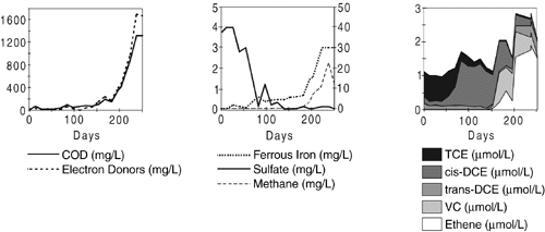
Figure 1. The Role
of Electron Donor Concentrations and Redox Conditions in the Complete Reductive
Dechlorination of TCE at TAN
Another remarkable observation was the impact of the operations on the residual source. The lactate additions greatly enhanced the bioavailability of the TCE. This was indicated by the formation of TCE degradation products far in excess of the original aqueous TCE concentrations, and by facilitated transport of high aqueous TCE concentrations that were subsequently transformed completely to ethene. INEEL has a patent pending on the in situ process used at TAN to enhance the bioavailability of nonaqueous chlorinated solvents. The demonstration of significant impact on the residual source of TCE opens a wide range of potential applications for enhanced in situ biodegradation where its effectiveness was previously thought to be quite limited. The success of the project in the complex fractured basalt aquifer at TAN may be a milestone both for fractured rock remediation and for in situ bioremediation of chlorinated solvent source areas.
For more information, contact Kent S. Sorenson (INEEL) at 208-526-9597 or E-mail SORENKS@inel.gov.
Enhanced In Situ Bioremediation Demonstrated in Fractured Bedrock
Vince Gallardo, U.S. Environmental Protection Agency, National Risk Management Research Laboratory
Introduction
The U.S. EPA’s Superfund Innovative Technology Evaluation (SITE) Program conducted a demonstration of the Enhanced In Situ Bioremediation Process at the ITT Industries Night Vision Facility in Roanoke, VA. The biostimulation process, developed by the U.S. Department of Energy and licensed to Earth Tech, Inc., involves injecting a mixture of air, gaseous phase nutrients, and/or methane into contaminated ground water to stimulate and accelerate the growth of existing microbial populations—especially methanotrophs. The methanotrophs produce enzymes that can degrade chlorinated solvents and their breakdown products.
The ITT facility is an active plant that produces night vision devices and related products. Ground water was contaminated with chlorinated and non-chlorinated volatile organic compounds (VOCs) due to solvent leaks from storage tanks. The site is underlain by a clay-rich overburden atop fractured shale and limestone bedrock at 5 to 10 feet below ground surface (bgs). Ground water is generally encountered at the overburden-bedrock interface and in the bedrock fractures. Trichloroethylene (TCE), 1,1,1-trichloroethane (TCA), and their breakdown products exceed Federal Maximum Contaminant Levels.
Design and Implementation
The primary components of the Enhanced In-Situ Bioremediation Process system are an injection well, air injection equipment, monitoring wells, and soil vapor monitoring points. At the ITT facility, methane was injected on a pulsed schedule from March 1998 to July 1999. The other gases were injected continuously. The radius of influence of the injection well was 40 feet. Four monitoring wells were within the radius of influence. One was upgradient, and one downgradient. In addition, there were four soil vapor monitoring points. Some monitoring wells were screened across the upper and lower zones of the bedrock; other wells were screened in either the upper or the lower zone (10.5 to 30.5 feet and 40 to 50 feet bgs, respectively).
The primary objective of the demonstration was to evaluate Earth Tech’s claim of a minimum 75 percent reduction in the concentration of critical analytes in the zone of influence after six months’ treatment. Four critical analytes were selected because they exhibited acceptable temporal and spatial variability: chloroethane (CA), cis-1,2- dichloro-ethylene (DCE), 1,1-dichloroethane (DCA), and vinyl chloride (VC). TCE did not exhibit acceptable variability. Baseline concentrations were measured at each of the four monitoring wells in the zone of influence for seven consecutive days; another seven-day sampling event was conducted 16 months later. The evaluation period was extended to 16 months due to process optimization and modifications.
Results and Conclusions
The results (see Tables 1 and 2) show that system performance varied with the depth of contamination. For the lower zone, treatment did not achieve the minimum 75 percent reduction for any of the critical analytes. This is believed to be due to insufficient oxygen, nutrient, and methane levels in the lower zone.
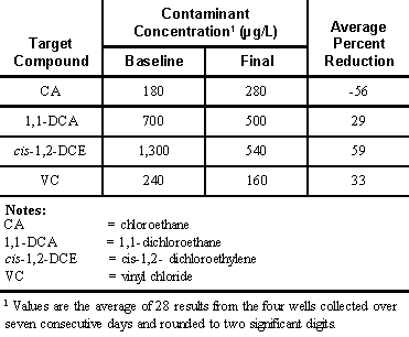
Table 1.
Ground-Water Results from Lower Zone
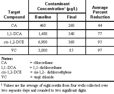
Table 2.
Ground-Water Results from Upper Zone
Contaminant reduction in the upper zone was markedly higher than the lower zone for all four of the critical analytes. Fewer samples were taken from the upper zone and do not represent a statistically valid sample set but still are useful in evaluating treatment of VOCs in fractures in the zone. The greater reduction in the upper zone suggests that the air/nutrient/methane mixture may have migrated towards the upper zone and effected greater treatment. This would also explain the lower reduction in the lower zone.
For further information, contact Vince Gallardo at 513-569-7176 or E-mail gallardo.vincente@epa.gov.
Innovative Techniques Used To Improve Mass Flux Calculations in Fractured Bedrock
by Christopher Gaule, Malcolm Pirnie, Inc.; Kenneth Goldstein, Malcolm Pirnie, Inc.; and Grant Anderson, U.S. Army Corps of Engineers
Background
Watervliet Arsenal in Watervliet, New York, is the United States’ oldest, continuously operating, cannon manufacturing facility. The 140-acre arsenal is located on the west bank of the Hudson River, about four miles south-southwest of its confluence with the Mohawk River. The property includes manufacturing facilities, administrative offices, a shipping yard, and a storage area for raw and hazardous materials, supplies, and finished goods. Ground water discharges to the Hudson River, along the eastern property boundary.
Contaminant Distribution
Early in the site investigation, bedrock monitoring wells ranging from 20 to 80 feet deep were installed at the arsenal in shallow and intermediate bedrock flow zones. Ground-water samples were analyzed for tetrachloroethene (PCE), trichloroethene (TCE), dichlorethene (DCE), and vinyl chloride (VC). The results indicated that volatile organic compounds (VOCs) had migrated downward in the bedrock and that reductive dehalogenation was occurring, as evidenced in the concentrations of TCE, DCE and VC. Dense non-aqueous phase liquid (DNAPL) was detected at a well located near the Hudson River, which is the regional ground-water discharge boundary. The DNAPL was detected 55 to 70 feet below ground surface (bgs).
Additional monitoring wells were installed to better define the lateral and vertical limits of VOC contamination in bedrock. The locations and target depths for the new wells were based on results of conventional borehole geophysical techniques and video logging, and the relatively new technique of enhanced digital Borehole Image Processing System (BIPS). BIPS collects images of the face of a borehole using a digital camera and provides real-time, two-dimensional displays. The use of BIPS allowed for better characterization of the bedrock fractures including orientation, aperture width, and frequency.
Discrete zone sampling of the wells also was conducted using a packer sampling installation. This technique allowed certain fractures to be sampled for chemical analysis as well as hydraulic head. A contaminant profile was then constructed for each well.
Results of the geophysical logging indicated a primary dip direction to the east at an average of 100 to 110 degrees. This corresponds to the primary direction of ground-water flow in the bedrock. Results of the video log, fluid resistivity data, and temperature log of the well with DNAPL indicated that a single significant fracture, 57 to 60 feet bgs, is the borehole’s contaminant-bearing fracture. The estimated fracture aperture is 0.70 mm. Packer sampling results indicated that the dissolved phase contamination extends more than 160 feet below grade at the eastern property boundary. Contamination to depths of about 160 feet bgs may be attributable to smaller fractures.
Subsequent packer sampling and geophysical logging of additional wells indicated that there are single fractures at discrete depth intervals contributing the majority of flow and contaminants.
Calculation of Mass Flux to the River
Contaminant mass flux from the bedrock will be calculated to estimate potential water quality impacts to the Hudson River (the discharge point) and to determine the need for mass flux reduction. Calculations of mass flux typically use the total cross-sectional area of the contaminant zone—which could be over 160 feet thick at this site—and the average or highest concentration detected. Geophysical and ground-water sampling results revealed that ground-water flow and the mass flux are generally confined to single fractures located at discrete vertical intervals in the bedrock. As a result, the contaminant flux from the bedrock should be estimated from a series of single fractures, rather than by using the entire cross-sectional area. Additional wells will be drilled, sampled, and logged in order to develop an accurate estimate of mass flux to the discharge boundary developed.
Mass flux calculations will be further refined with pumping test data to determine the degree of interconnection and the hydraulic conductivity of the fractures. For more information, contact Grant Anderson (U.S. Army Corps of Engineers) at 410-962-6645 or e-mail Grant.A.Anderson@nab02.usace.army.mil or Kenneth Goldstein (Malcom Pirnie) at 914-694-2100, or e-mail KGoldstein@pirnie.com.
| Mention of trade or commercial products does not constitute endorsement by the U.S. Environmental Protection Agency. |
|
|