Environmental Fracturing
Overview
- Overview
- Comparison of Environmental and Shale Gas Hydrofracturing
- Guidance
- Application
- Additional Resources
Environmental fracturing technologies are techniques that enhance or create openings in bedrock or soil with low effective porosity, such as clay, to help soil and groundwater cleanup methods work better. The enhancements are referred to as secondary porosity fractures and joints. Environmental fracturing can be used to make primary treatment technologies such as pump and treat (P&T), in situ chemical oxidation/reduction (ISCO/ISCR), in situ bioremediation, or soil vapor extraction (SVE) more efficient.
For example, by providing better fracture connectivity across a contaminated bedrock area, fracturing can lead to fewer P&T extraction wells that need to be installed and the wells can be pumped at a higher rate.
SVE depends on the ability of contaminants to be drawn through the vadose zone to an extraction well where they can be treated at the surface. Contaminated areas with low effective porosity transmit soil gas very slowly thus extending the potential remediation time. Fracturing can create multiple avenues of secondary porosity for contaminant migration within the low effective porosity soil that can speed up cleanup.
Many in situ cleanup technologies require the use of amendments, such as chemical oxidants, reductants, or biologically stimulating agents and microbes. These amendments depend upon direct contact to treat or stabilize contaminants of concern. In soil with low effective porosity, the amendments will often follow subtle preferential pathways that avoid contact with much of the contaminant volume. Fracturing can establish a network of preferential pathways within the contaminated soils that allows treatment of areas that were not directly accessible before. Fracturing is also applicable to some instances where back diffusion of contaminants trapped in the aquifer matrix is an issue.
Remediation amendments can be placed in the subsurface using fracturing or injection techniques. Injection is the process of permeating the primary matrix or secondary fracture system network with remedial agents without changing the matrix or fracture structure (Bures 2009, Christiansen 2010). Injection is usually done in more permeable soils or in rock formations where the decision is made that the existing fracture network is adequate for reaching remedial goals. Injection technologies are not addressed in this focus area.
There are three primary fracturing technologies: hydraulic fracturing, pneumatic fracturing, and blasting.
Jump to a Subsection
Hydraulic Fracturing |
Pneumatic Fracturing |
Blasting |
Additional Information |
Performance Monitoring for Hydraulic and Pneumatic Fracturing
|

![]()
Figure 2. Hydraulic Fracturing in Unconsolidated Soils
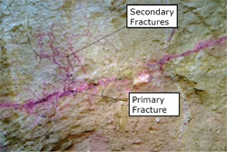
Environmental hydraulic fracturing uses water or a water-based fluid to induce fractures. In unconsolidated subsurface materials (clays and silts) a borehole is advanced to the depth where the fracturing will occur. Generally the borehole is cased to this depth (usually accomplished using a hollow stem auger or dual tube direct push rig) and a high pressure (≈ 3,000 psi) water nozzle is inserted (Murdoch and Slack 2002). The water pressure forms a disk shaped nucleation zone at the base of the casing (Figure 2). (Note that the orientation of the primary fracture zone can be directed by the orientation of the nozzle [Slack 2000]) The nozzle is withdrawn, a packer is installed above the notch, and fluid pressure is applied to the nucleation zone to initiate fracturing. The pressure needed for the initiation is typically low (less than 100 psi) and falls as the fracture propagates (Susthersan 1999, EPA 1994). Depending upon the material being fractured the radius of influence for a fracture well in unconsolidated materials is 20 to 35ft (Susthersan 1999).
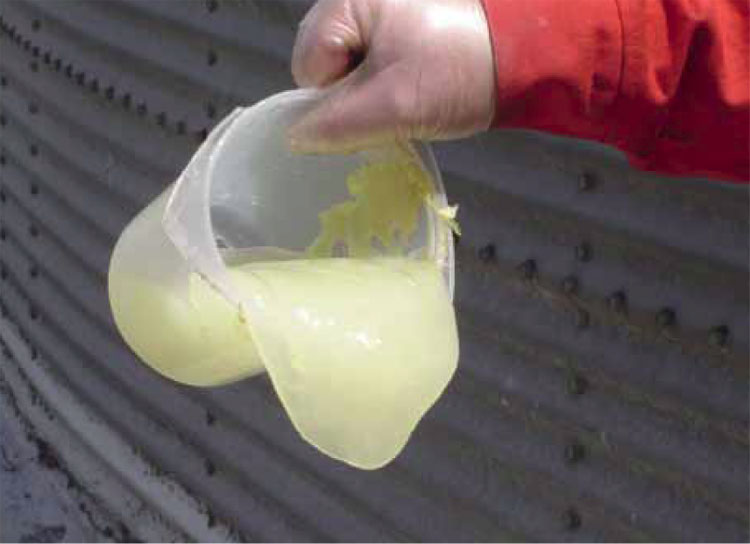
A commonly used hydraulic fluid is a guar gum gel water mixture (Susthersan 1999, EPA 1994). The viscosity of the gel (Figure 3) is sufficient for it to act as a carrying fluid for fracture propping agents such as coarse sand or in some cases ZVI (Figure 4). The gel contains a crosslinker (borate salts) for greater viscosity and an enzyme that allows it to degrade over time leaving the now permeable fracture propping agents in place (Figure 5). The propped open fractures are used for enhancing recovery of P&T and SVE systems or for delivery of remediation amendments. (See Hydraulic Fracturing Photos.)
In bedrock settings the goal is generally to enlarge the existing fracture network, although initiating new fractures can be done (Suthersan 1999)—especially in bedded formations (sandstone, shale, limestone). To do this straddle packers are typically set across the area to be fractured or enlarged (EPA 1994, Bures 2010). As with unconsolidated hydrofracturing, water or a water-based fluid is introduced to the packed off zone and pressurized until a fracture is nucleated and/or begins propagation. The pressure required for nucleation is generally higher than that for propagation. Bures et al. (2010) report fracturing in sedimentary bedrock using guar gum/sand/ZVI slurry at depths between 35 and 63 ft bgs with radii of influence greater than 30 ft. Break pressures for the fractures ranged from 124 to 838 psi with propagation pressures ranging from 140 to 700 psi.
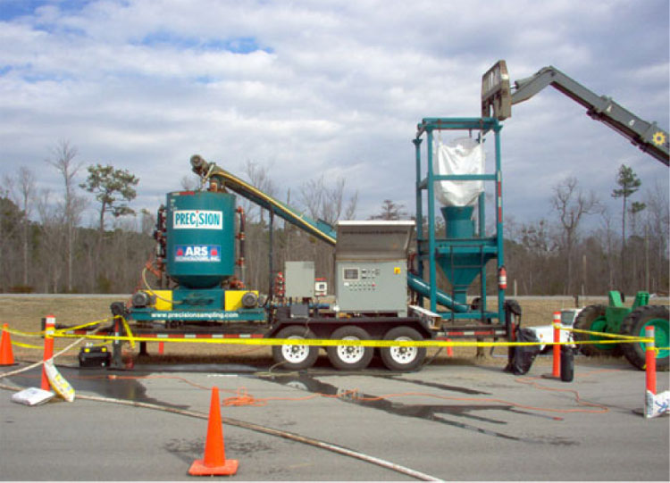
Hydraulic Fracturing Photos


![]()
Figure 6. Pneumatic Nitrogen Injection System (Source NAVFAC)
Pneumatic fracturing uses air or other gas to induce and propagate fracturing. Typically, pneumatic fracturing is used in formations where the fractures will remain open for a long time without support, hence propping agents to hold fractures open are not commonly employed. The major components of a pneumatic fracturing system include compressed gas supply, a flow pressure system, a flow-pressure regulation system, and an injector (Suthersan 1999 DOE 1998). Figure 6 is a nitrogen-based pneumatic fracturing setup at the Hunters Point Naval Shipyard (Kito 2010).
Typically, an individual pneumatic fracture is accomplished by (1) advancing a borehole to the desired depth of exploration and withdrawing the auger, (2) positioning the injector at the desired fracture elevation, (3) sealing off a discrete 1 or 2 ft interval by inflating the flexible packers on the injector with nitrogen gas, (4) applying pressurized air for approximately 30 seconds (or less), and (5) repositioning the injector to the next elevation and repeating the procedure (Suthersan 1999). Packers can be deployed in two fashions. If the formation is such that it will collapse around the core barrel and provide a strong seal, a single packer can be used within the barrel for a seal to the surface and gas injected below it. In formations that might not collapse (bedrock, clay) straddle packers might be deployed with gas introduced between them. Pneumatic fracturing can be used to place solid reactive agents or atomized solutions. (See Forman et al. 2010 for an example of both.)
Pneumatic Fracturing Photos
Photos from Appendix D of Pilot Study Report Site 35, Operable Unit No. 10 Marine Corps Base Camp Lejeune, North Carolina NAVFAC, 264 pp, 2006


Advantages
- Both hydraulic and pneumatic fracturing can increase the recovery of pump & treat systems and SVE as well as improve LNAPL recovery rates (EPA 1994), potentially decreasing cleanup time.
- Injection of amendments, such as a permanganate solution, which have the ability to diffuse into tight matrices (clay, sandstone) before being depleted, can access contaminants that are unreachable with technologies other than thermal.
Limitations
- Hydraulic/pneumatic fracturing may be limited in areas with structures or utilities within the intended fracturing area because of potential damage caused by heave (Suthersan 1999).
- Environmental hydraulic/pneumatic fracturing generally has not been applied at depth (>100 ft).
Blast-enhanced fracturing is a technique used at sites with fractured bedrock formations to improve the rate and predictability of recovery of contaminated groundwater, or in some cases, contaminated vapors through use of SVE. The increased well yields, hydraulic conductivity values, and capture zones that result from use of this technique occur as a result of creation of a "fracture trench" or highly fractured rubble zone created through detonation of explosives in boreholes (called shotholes). Pumping/recovery wells installed into this area can capture greater quantities of groundwater, intercepting flow from fractures to which they did not previously have a hydraulic connection. The number, location, and spacing of shotholes are determined through interpretation of site characterization data, usually including aquifer testing for groundwater recovery (Miller 1996).
Advantages offered by blast-enhanced groundwater recovery include the following (adapted from Miller 1996):
- Increased hydraulic conductivity can reduce the number of recovery wells required to be installed to achieve effective remediation and hydraulic containment. Requiring fewer recovery wells will decrease well installation and operation and maintenance costs, including redevelopment and pump replacement.
- Increased well yield can shorten the time period necessary to achieve remediation objectives.
- Verifying contaminant capture is easier since after fracturing, the recovery well can be directly connected to fractures along the entire cross section of fracture zone. At the Modern Landfill site in York, PA the blasted bedrock trench is over 30 meters deep, up to 10 meters wide and 860 meters long. The rock blasting created new fractures and widened nearby existing fractures, increasing bedrock porosity from less than 1 percent to 10 percent, and increasing hydraulic conductivity from 10-4/ 10-5 to 10-2 cm/sec. (Smerekanicz et al. 2004).
References:
![]() EPA. 1994.
EPA. 1994.
Manual: Alternative Methods for Fluid Delivery and Recovery
EPA/625/R-94/003, 96 pp
Kito, M. 2010.
Results from Zero-Valent Iron Treatability Study for TCE and Chloroform Reduction at Hunters Point Shipyard, CA (PPT 26 slides)
Seventh International Conference on Remediation of Chlorinated and Recalcitrant Compounds (Monterey, CA; May 2010)
![]() Artificially-Induced or Blast-Enhanced Fracturing to Improve Groundwater Recovery for Treatment and Migration Control: Technology Overview Report
Artificially-Induced or Blast-Enhanced Fracturing to Improve Groundwater Recovery for Treatment and Migration Control: Technology Overview Report
1996. Ralinda R. Miller, Ground-Water Remediation Technologies Analysis Center. TO-96-01, 13 pp.
The report introduces the principles and techniques associated with fracturing and discusses the advantages and disadvantages of the technology in remediation applications.
![]() Cost and Performance Report Nanoscale Zero-Valent Iron Technologies for Source Remediation
Cost and Performance Report Nanoscale Zero-Valent Iron Technologies for Source Remediation
Gavaskar, Arun, Lauren Tatar, and Wendy Condit
NAVFAC, 54 pp, 2005
This report contains a discussion of pneumatic fracturing and delivery of an iron water slurry at Hunters Point Naval Shipyard.
Forms of Hydraulic Fractures in Shallow Fine-Grained Formations
Journal of Geotechnical and Geoenvironmental Engineering, 2002
This paper discusses fracture orientation produced by hydraulic fracturing in unconsolidated fine-grained soil.
Hydraulic Pneumatic Fracturing
Purdue University, Division of Construction Engineering and Management, Emerging Construction Technologies Website.
This fact sheet provides a brief overview and background on fracturing techniques used in environmental remediation.
Superfund Remedy Report, 17th Edition
EPA 542-R-23-001, 2023
This report discusses remedy selection and selection trends at Superfund NPL sites.
Performance Monitoring for Hydraulic and Pneumatic Fracturing
There are two aspects to performance monitoring in hydraulic/pneumatic fracturing. The first is determining the success in fracturing the target subsurface area. The second is determining whether the fracturing increased the vadose or saturated zone conductivities to the planned levels or if the amendments that were added during or after the fracturing are performing as planned. This section will only discuss the first aspect. Performance monitoring for various amendments is covered in their individual focus sections (e.g., in situ chemical oxidation, bioremediation, in situ reduction, thermal or in the DNAPL Technologies Section.
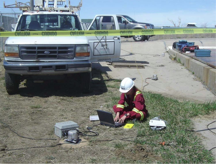
![]()
Tiltmeters in Fracture Area (Courtesy: FracRite Environmental)
The following are typically used for interpreting hydraulic/pneumatic fracture size and orientation in the subsurface.
- Continuous monitoring of injection well pressure. Can provide real time information about fracture orientation.
- Measurement of the displacement of the ground surface (heave). Usually accomplished with surveying equipment. Heave detection can be used to estimate the dimensions of both aperture and length of fractures (Suthersan 1999).
- Measurement of the angular deformation of the ground surface. This is done using tiltmeters and the information can be used to create 3-D mapping of the fractures. See Bures et al. (2010) for an example.
- Measurement of head or pressure differences in off-set monitoring wells. These pressure differences can usually be measured with pressure tranducers fitted in the wells.
- In unconsolidated materials, direct push continuous coring techniques can provide visual evidence of fracture size, orientation, and proppant or amendment presence.
References:
Suthersan, S. 1999.
Hydraulic and Pneumatic Fracturing in Remediation Engineering: Design Concepts
Suthersan, S. ed
CRC Press, Boca raton, 1999