This chapter presents a number of basic concepts regarding surfactants, cosolvents, and other chemical agents that may be used with them. In general, surfactants are used to both increase the total aqueous solubility of a NAPL such that the dissolution process is accelerated and to decrease NAPL-water interfacial tension such that physical mobilization of the NAPL takes place. By tailoring the chemical structure of the surfactant to the composition of the NAPL, either the accelerated dissolution mechanism, the physical mobilization mechanism, or both can be emphasized. In all cases, the surfactant is injected as part of an aqueous solution and flushed through the region of the subsurface containing residual and pooled NAPL.
Cosolvents are chemical agents that can be used to enhance the performance of surfactants. They also can be used on their own to bring about either enhanced NAPL dissolution or physical NAPL mobilization. The main cosolvents being considered for environmental applications are water-miscible alcohols. When alcohols are injected at high concentrations, the term alcohol flooding is usually used rather than the term cosolvent flooding. Cosolvent flooding generally refers to the injection of low alcohol concentrations. As with surfactants, cosolvents such as alcohol are injected as part of an aqueous solution and flushed through the region of the subsurface containing residual and pooled NAPL.
Relevance
This section describes the basic properties and structure of surfactants. Readers who would like to understand the physical and chemical processes that occur during a surfactant flood should read this section. Those with good knowledge of surfactant chemistry and the application of surfactants in subsurface systems may choose to skip this section.
Key Concepts
• Surfactants are chemical agents that alter the properties of solution interfaces. They can be added to an aqueous solution and injected into an aquifer to bring about both an increase in NAPL solubility and a decrease in NAPL-water interfacial tension.
• The increase in total aqueous solubility that occurs in a surfactant system is always associated with a decrease in interfacial tension.
• Surfactants chosen to increase NAPL solubility without achieving ultra-low interfacial tensions are employed in a solubilization flood. Surfactants chosen to achieve ultra-low interfacial tensions are employed in a mobilization flood. Solubilization surfactants may still lower interfacial tension enough to cause some NAPL mobilization.
• Surfactant molecules have both a hydrophilic and a hydrophobic portion, and are generally classified as either anionic, cationic, or nonionic.
• The relative influence of the hydrophilic and hydrophobic portions of the surfactant molecule can be characterized by the surfactant charge density and the hydrophile-lipophile balance (HLB) number.
• If sufficient surfactant is added to aqueous solution, aggregations of surfactant monomers called micelles will form. This occurs at the critical micelle concentration (CMC). A thermodynamically stable solution of micelles is referred to as a microemulsion.
• Contaminants can partition into the interior of the micelle, thereby increasing the total aqueous solubility of the contaminant by a process referred to as micellar solubilization.
• The degree of solubility enhancement achieved by a surfactant can be characterized by the micelle-water partition coefficient and the molar solubilization ratio (MSR).
• Care should be taken in utilizing equilibrium partitioning relationships when designing a surfactant flood because the solubilization process is rate-limited for some systems.
• The degree of interfacial tension lowering required to mobilize NAPL can be characterized by the capillary number, the bond number, and the total trapping number.
• The distribution of surfactant and fluid phases in a surfactant - water - NAPL system can be characterized by ternary phase diagrams. Depending on the surfactant selected and the aqueous phase chemistry, either a Winsor Type I, Type II, or Type III system will result. The Winsor Type III system is associated with a middle-phase micro-emulsion and ultra-low interfacial tensions.
• The performance of a surfactant in the subsurface is dependent on temperature, sorption, degradation, the aqueous geochemistry of the injection water, and the surface chemistry of aquifer solids.
Surface active agents, or surfactants, are chemical compounds that have the potential to alter the properties of fluid interfaces. Although the use of surfactants to remediate organic contaminants in the subsurface is a relatively new area of application, their use in subsurface systems dates back to 1963 when petroleum sulfonates were patented for widespread use in enhanced oil recovery efforts (Pope and Wade, 1995).
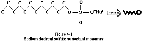
The surfactant molecule is typically composed of a strongly hydrophilic (water loving) group, or moiety, and a strongly hydrophobic (water fearing) moiety (West and Harwell, 1992). The entire surfactant monomer is often referred to as amphiphilic because of its dual nature. The hydrophobic portion of the surfactant monomer is typically a long hydrocarbon chain, referred to as the "tail" of the molecule. The hydrophilic "head" group often includes anions or cations such as sodium, chloride, or bromide. The surfactant monomer is illustrated as a tadpole structure in Figure 4-1. The molecular weight of surfactants under consideration for environmental applications typically ranges from 200 g/mol to 2000 g/mol.

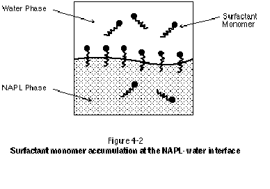
The hydrophilic group of the surfactant monomer provides most surfactants with a high solubility in water. The hydrophobic group of the monomer, however, prefers to reside in a hydrophobic phase such as LNAPL or DNAPL. These competing effects result in the accumulation or congregation of surfactant monomers at NAPL-water interfaces, with the hydrophobic tail group embedded in the NAPL phase and the hydrophilic head group oriented toward the water phase. This is illustrated in Figure 4-2. As with the NAPL-water interface, surfactant accumulation also occurs at water-air and water-solid interfaces.
Surfactants can be generally classified according to the nature of their hydrophilic head group. Anionic surfactants give rise to a negatively charged surfactant ion (hence anionic) and a positively charged counterion upon dissolution in water. Examples of anionic surfactant groups include sulfonic acid salts, alcohol sulfates, alkylbenzene sulfonates, phosphoric acid esters, and carboxylic acid salts. Anionic surfactants tend to be good solubilizers and are relatively nontoxic. They have been used in petroleum oil recovery operations as well as in contaminant hydrogeology remediation applications.
Cationic surfactants yield a positively charged surfactant ion (hence cationic) and a negatively charged counterion upon dissolution in water. Examples include polyamines and their salts, quaternary ammonium salts, and amine oxides. Cationic surfactants tend to be toxic and are therefore not widely used in environmental applications at this time. Cationic surfactants also tend to sorb to anionic surfaces and so can be severely retarded in groundwater systems.
Nonionic surfactants are characterized by hydrophilic head groups that do not ionize appreciably in water. Examples include polyoxyethylenated alkylphenols, alcohol ethoxylates, alkylphenol ethoxylates, and alkanolamides. Nonionic surfactants tend to be good solubilizers and are relatively nontoxic. They are usually easily blended with other types of surfactants (i.e., used as cosurfactants) and therefore have found widespread use in petroleum and environmental applications. The performance of nonionic surfactants, unlike anionic surfactants, is relatively insensitive to the presence of salts in solution.
In some cases, the primary objective of a surfactant flood will be to bring about enhanced solubilization of the NAPL. In a solublization flood, the total aqueous solubility of the contaminant is increased such that the dissolution process becomes more efficient. Physical mobilization of the residual and pooled NAPL may be undesirable in a solubilization flood. Rather, the goal of a solubilization flood is to dissolve away residual and pooled NAPL in fewer pore volumes than would be required by natural groundwater flow or pump-and-treat systems alone.
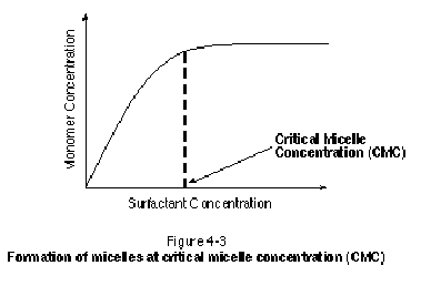
As surfactants are added to aqueous solution, they will tend to accumulate at fluid-fluid and fluid-solid interfaces. Some surfactant monomers also will exist in free solution in all phases present. Once a sufficient amount of surfactant has been added to aqueous solution, however, aggregations of surfactant monomers referred to as micelles will form. Micelles are often spherical in shape and can contain several hundred surfactant monomers. As shown in Figure 4-3, the threshold concentration at which micelles begin to form is termed the critical micelle concentration (CMC). Beyond the CMC, any surfactant added to aqueous solution will not increase the number of monomers in aqueous solution, but rather will contribute to the formation of additional micelles.
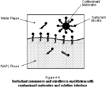
The surfactant monomers comprising a micelle formed in aqueous solution are generally oriented with their hydrophobic tail groups pointed toward the interior of the micelle. This renders a hydrophobic interior to the micelle within which organic molecules can reside, thereby increasing the total aqueous solubility of the contaminant. This is referred to as micellar solubilization (Abriola, et al., 1995) and is the primary objective in a "solubilizing" surfactant flood. By increasing the total aqueous solubility of the target NAPL, dissolution of the NAPL will be accelerated. Surfactant monomers in solution and monomers at solution interfaces will be in equilibrium with monomers in micelles, with a continuous movement of monomers between these various sites. This is illustrated schematically in Figure 4-4.
The concentration of surfactant required to form micelles is typically small and is dependent on factors such as surfactant type, temperature, and water hardness (Rosen, 1989). Table 4-1 lists the CMC of several surfactants. In general, increasing the nonpolar molecular weight of the surfactant, decreasing the number of branches of the hydrophobic chain, and decreasing the number and strength of the hydrophilic head groups will increase the solubility of organics in solution. As the hydrophobicity of the surfactant increases, its CMC in aqueous solution will generally decrease. The CMC is typically between 10 mg/L and 2,000 mg/L.
The behavior of surfactants in groundwater systems is sensitive to
temperature. The temperature at which the aqueous solubility of an ionic
surfactant equals the CMC is referred to as the Krafft point. Below the
Krafft point, micelles will not form and the surfactant solution will have no
solubilization potential. The Krafft point should be evaluated through
laboratory testing. It can be somewhat manipulated by using cosurfactants and
changing the branching structure of the hydrophobic tail group of the
surfactant monomer.
| Table 4-1 |
||
| CMC of Typical Surfactants in Aqueous Solution |
||
| Surfactant | CMC (mg/L) |
Reference |
|---|---|---|
| |
||
| Witconol 2722 |
13 |
Pennel, et al. (1993) |
| Triton X-100 |
130 |
Kile and Chiou (1989) |
| Triton X-114 |
110 |
Kile and Chiou (1989) |
| Triton X-405 |
620 |
Kile and Chiou (1989) |
| Brij 35 |
74 |
Kile and Chiou (1989) |
| Sodium dodecyl sulfate |
2100 |
Kile and Chiou (1989) |
| Synperonic NP4 |
23.7 |
Narkis and Ben-David (1985) |
| Marlophen 86 |
32.5 |
Narkis and Ben-David (1985) |
| Synperonic NP9 |
48.9 |
Narkis and Ben-David (1985) |
| Marlophen 810 |
55.4 |
Narkis and Ben-David (1985) |
| 1:1 blend Rexophos 25/97, Witconol NP-100 |
2000 |
Longino and Kueper (1995) |
Nonionic surfactants are subject to coacervation at high temperatures. This refers to the formation of a separate surfactant-rich phase at the cloud point (Rosen, 1989). Precipitation of the surfactant in this manner is undesirable because it will lower the amount of surfactant available in aqueous solution for micellar solubilization. The cloud point should be evaluated through laboratory testing. Thermodynamically stable liquid crystals also can form depending on the type of contaminant present, the temperature, the structure of the surfactant, and the type and concentration of electrolytes present in solution. The formation of liquid crystals can occur at low temperatures and represents a significant surfactant loss mechanism that needs to be evaluated on a site-by-site basis in order to ensure successful surfactant performance. The formation of liquid crystals also can impact the viscosity of the surfactant solution, thereby affecting the flow properties of the injected chemical solution. Liquid crystal formation can be prevented through the addition of a cosolvent or cosurfactant (Baran, et al., 1994a). The precipitation of surfactants in aqueous solution is discussed further by Sabatini, et al. (1995); Rouse, et al. (1993); and Jafvert and Heath (1991).
The relative influence of the hydrophilic and hydrophobic portions of the surfactant monomer can be used as an indicator of the surfactant’s potential performance. The relative influence can be characterized by the surfactant charge density, which is the ratio of the number of dissociated ions per surfactant molecule to the molecular size of the molecule. The solubility of a surfactant in aqueous solution generally increases with increasing charge density.
The hydrophile-lipophile balance (HLB) number is an indication of the relative strength of the hydrophilic and hydrophobic portions of the molecule and can be used to characterize the relative affinity of surfactants for aqueous and organic phases (Sabatini, et al., 1995). A high HLB number generally indicates good surfactant solubility in water, while a low HLB number indicates a lower aqueous solubility and higher relative affinity for the organic phase (e.g., NAPL). A surfactant with a low HLB number can partition significantly into the NAPL phase and form reverse micelles having hydrophilic interiors and lipophilic exteriors (Sabatini, et al., 1995). The presence of reverse micelles in the NAPL phase is characteristic of a Winsor Type II system (Lake, 1989); this is discussed further below. For a particular organic contaminant, optimum aqueous phase solubilization will generally occur at a specific HLB number. Less hydrophobic contaminants (those that are more water soluble) generally require a higher HLB number surfactant to bring about sufficient solubilization. HLB numbers for surfactants having environmental application are reported by various authors, including Vigon and Rubin (1989); Diallo, et al. (1994); Intera and SUNY (1995); and Sabatini, et al. (1995).
Whenever a surfactant is added to an aqueous solution, a number of property changes occur, as illustrated in Figure 4-5. Air-water surface tension will decrease upon addition of the surfactant to the solution, reaching a minimum at the CMC. Similarly, NAPL-water interfacial tension will decrease, also reaching a minimum at the CMC. Both the surface tension and the interfacial tension remain relatively unchanged from these minimum values as surfactant concentration is increased beyond the CMC. The degree of interfacial tension lowering associated with the use of surfactants has been explored by various authors, including Fountain, et al. (1991) and Longino and Kueper (1995). The study by Longino and Kueper (1995) involved a surfactant-NAPL system where interfacial tension was observed to decrease over time. In general, solubilizing surfactants will lower NAPL-water interfacial tension to between 1 dyne/cm and 5 dynes/cm. Although this degree of interfacial tension lowering is not sufficient to bring about significant mobilization of residual NAPL, it may be sufficient to bring about vertical mobilization of pooled NAPL.
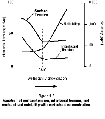
Figure 4-5 also illustrates that the solubility of organics in solution increases dramatically beyond the CMC as additional micelles are formed. This solubility is actually a "total" solubility because it represents contaminant molecules in free aqueous solution as well as contaminant molecules entrained in micelles. In some instances, the micelle can be thought of as a separate phase into which contaminant partitioning can occur. In general, the larger the KOW (the octanol-water partition coefficient) of a particular contaminant, the greater its tendency to partition into the micellar phase. It is the dramatic increase in contaminant solubility beyond the CMC that renders surfactant flushing a promising technology for NAPL remediation. The micellar solubilization process has been shown to bring about a 10- to 100-fold increase in the aqueous solubility of common organic contaminants.
Jafvert, et al. (1995) evaluated the solubilization of hexachlorobenzene by a variety of surfactants. Figure 4-6 presents the results of this study and shows clearly that the degree of solubility enhancement (on a mass basis) is dependent upon the particular surfactant chosen. Jafvert, et al. (1995) also present the following equation to relate the octanol-water partition coefficient, KOW, to the micelle-water partition coefficient, Km:
Km=ßKow (1)
where ß is dependent on the particular surfactant of interest, and Km is defined as the molar ratio of the contaminant in the micellar phase divided by the molar ratio of the contaminant in the aqueous phase. Jafvert, et al. (1995) list values of ß and Km for several surfactant-organic systems. Valsaraj and Thibodeaux (1989) report a linear relationship between logKm and logKow for eleven organic compounds solubilized by an anionic surfactant (sodium dodecyl sulfate). Edwards, et al. (1991) report a linear relationship between logKm and logKow for the solubilization of polycyclic aromatic hydrocarbons (PAHs) by nonionic surfactants.
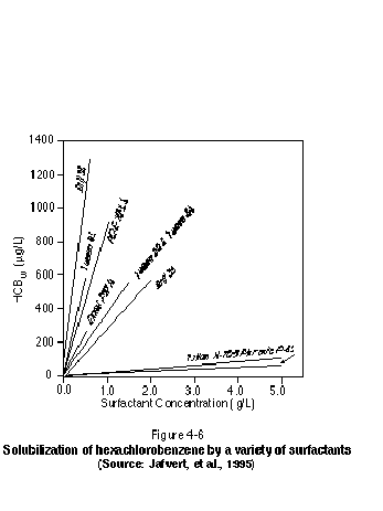
In addition to the micelle-water partition coefficient, the degree of solubility enhancement achieved with a particular surfactant can be characterized by the molar solubilization ratio (MSR). The MSR is defined as the moles of contaminant solubilized per mole of surfactant. It corresponds to the straight line slope above the CMC on a plot of aqueous contaminant solubility versus surfactant concentration. A higher MSR indicates a greater solubilization ability for the surfactant under consideration. Because the MSR is a function of temperature, solubilization screening studies should be carried out at the subsurface temperature of interest.
Shiau, et al. (1995) measured the solubilization parameters for tetrachloroethylene (PCE), trichloroethylene (TCE), and 1,2-dichloroethylene (1,2-DCE) using a variety of surfactants. These chlorinated organics were chosen because they differ in their degree of hydrophobicity (PCE>TCE>1,2-DCE). Table 4-2 presents both the MSR and logKm for these compounds. Note that for a particular surfactant, PCE experiences a higher degree of partitioning into micelles (higher logKm values) than TCE or 1,2-DCE, consistent with the fact that PCE is the most hydrophobic (lowest aqueous solubility) of these three compounds. More efficient solubilization can sometimes be achieved through the use of surfactant mixtures. Fountain, et al. (1996), for example, discuss the use of blended surfactants to optimize behavior for environmental applications.
A typical screening study for a field application may involve evaluating the performance of more than 100 surfactants. This is especially true for multicomponent NAPLs where a variety of chemical constituents need to be solubilized in an optimum manner. As will be discussed in Chapter 5, screening studies from similar sites can be used to get a "ball-park" indication of the types of surfactants that may be applicable at a particular site. Even if two sites are thought to contain identical types of NAPL, however, a surfactant screening study should be carried out for each site because of the influence of groundwater geochemisty and aquifer solid chemistry on surfactant behavior.
| Table 4-2 |
|||
| Molar Solubilization Ratio (MSR) and logKm for Tetrachloroethylene (PCE), Trichloroethylene (TCE), and 1,2-Dichloroethylene for a Variety of Surfactants |
|||
| Contaminant | Surfactant |
MSR |
logKm |
|---|---|---|---|
| PCE |
SDS |
0.39 |
4.5 |
| T-MAZ 28 |
0.45 |
4.55 |
|
| T-MAZ 20 |
2.27 |
4.9 |
|
| T-MAZ 60 |
3.15 |
4.94 |
|
| TCE |
SDS |
0.34 |
3.27 |
| T-MAZ 28 |
1.68 |
3.66 |
|
| T-MAZ 20 |
3.29 |
3.75 |
|
| T-MAZ 60 |
3.95 |
3.77 |
|
| 1,2-DCE |
SDS |
1.37 |
2.76 |
| T-MAZ 28 |
2.46 |
2.85 |
|
| T-MAZ 20 |
7.49 |
2.95 |
|
| T-MAZ 60 |
6.91 |
2.94 |
|
Source: Shiau, et al., 1995. |
|||
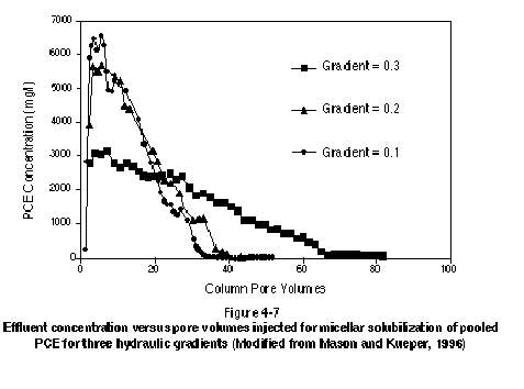
Laboratory experiments (Pennel, et al., 1993; Abriola, et al., 1993; Longino and Kueper, 1995; Mason and Kueper, 1996) and field experiments (Fountain, et al., 1996) have demonstrated that the micellar solubilization process can be rate-limited. These studies have shown that the rate at which NAPL is solubilized depends on a number of factors, including groundwater velocity and the NAPL-water interfacial area. The implication is that equilibrium batch solubilization measurements may not be adequate for the prediction of surfactant performance in field applications (Abriola, et al., 1995). Figure 4-7 presents data from Mason and Kueper (1996) in which pooled PCE was solubilized in a one-dimensional column using a blended surfactant mixture. The figure clearly shows that the highest effluent concentrations occur early on, followed by a gradual tailing toward lower concentrations. The figure also demonstrates that higher peak concentrations and a shorter tailing period (in terms of pore volumes, not necessarily time) are associated with slower groundwater velocities. This demonstrates that slow groundwater velocities give rise to a more efficient remediation process, where efficiency is related to the volume of contaminated water removed from the subsurface.
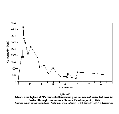
Similar tailing behavior was found in the field experiment conducted by Fountain, et al. (1996) using the same surfactant mixture as that employed in Figure 4-7. The experiment conducted by Fountain, et al. (1996) involved the solubilization of residual and pooled PCE in a natural sand aquifer located at Canadian Forces Base Borden. Figure 4-8 presents a plot of effluent concentration versus pore volumes. The plot demonstrates that the highest effluent concentrations occur early, followed by a gradual tailing toward lower concentrations. It is likely that the high effluent concentrations early on are the result of mass removal from the relatively higher permeability lenses, and that the later tailing is due in part to diffusion-limited mass transfer from relatively low-permeability lenses. Rate-limited mass transfer may also have occurred in the high permeability regions, consistent with what has been observed in the laboratory studies discussed above. It is important to note that in this field experiment, immiscible-phase DNAPL was still present in the experimental cell at the termination of the surfactant flood when effluent concentrations were no longer decreasing.
The practical implication of nonequilibrium mass transfer between NAPL and surfactant solution is that removing a specified mass of NAPL will require more time than calculated using equilibrium partitioning relationships. Equilibrium partitioning relationships should be used with caution because this procedure will significantly underestimate the amount of time and mass of surfactant required to solubilize a given volume of NAPL. Nevertheless,
equilibrium partitioning is an important consideration in comparing and selecting suitable surfactants. If the design of a system based on equilibrium partitioning results does not appear optimistic, there will be no need to proceed with a more sophisticated non-equilibrium analysis. To estimate the time required to execute a surfactant/cosolvent flood, a nonequilibrium mass transfer model could be used to calculate the number of pore volumes (and therefore the time period) of surfactant solution that will be required in a remediation effort. The use of numerical simulation for the design of surfactant/cosolvent floods is discussed further in Section 5.4.
The reduction in NAPL-water interfacial tension arising from the addition of a surfactant to an aqueous solution will reduce the influence of capillary forces. Capillary forces are responsible for the retention of residual NAPL and for the formation of pooled NAPL. If the interfacial tension can be lowered sufficiently, physical mobilization of NAPL can occur. This may be desirable for the case of an LNAPL where free product can be recovered in the vicinity of the watertable using skimmer wells, but may be undesirable in the case of a DNAPL where a lowering of interfacial tension may result in vertical mobilization of DNAPL deeper into the subsurface.
The degree of interfacial tension reduction required to mobilize residual NAPL can be best characterized by the capillary number. The capillary number represents the ratio of viscous (mobilizing) forces to capillary (resisting) forces and can be defined as follows:
![]() (2)
(2)
where NC is the capillary number, r is the density of water, g is the acceleration due to gravity, J is the hydraulic gradient (defined as Ñh earlier), and s is the NAPL-water interfacial tension. Figure 4-9 presents the relationship between capillary number and degree of residual reduction for both a typical sandstone and a packing of spherical beads. A typical porous medium, such as a fine- or medium-grained sand, will lie between these two end-member curves. Either an increase in hydraulic gradient or a reduction in interfacial tension is required to bring about an increasing degree of residual mobilization.
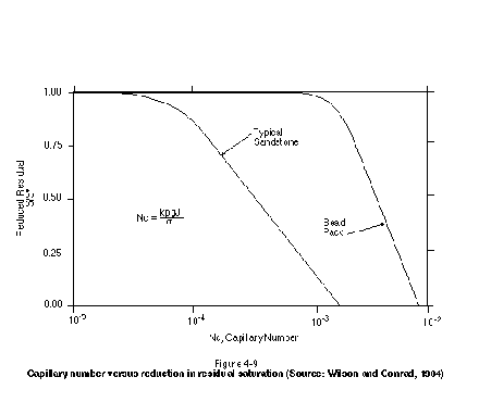
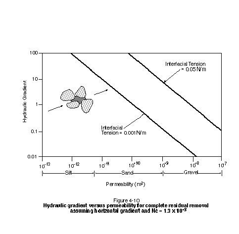
Figure 4-10 presents the relationship between hydraulic gradient and permeability for complete residual removal using the sandstone data from Figure 4-9. This plot should be viewed as extremely optimistic when applied to unconsolidated media because the sandstone parameters provide for easier mobilization than would a typical sand. Despite the use of favorable parameters, Figure 4-10 illustrates that extremely high hydraulic gradients will be required to mobilize significant amounts of residual. In practice, a hydraulic gradient in excess of approximately 0.5 will be difficult to sustain over large distances. It is clear that a reduction in interfacial tension is required if significant residual mobilization is to take place in media finer than a coarse sand or gravel.
Figure 4-10 indicates that for a hydraulic gradient of 0.5, the interfacial tension will need to be reduced to well below 0.001 N/m to bring about complete residual mobilization in a medium sand or finer-grained medium. The degree of lowering of NAPL-water interfacial tension that will occur upon exposure to surfactants depends strongly on the particular NAPL-surfactant combination. While all conventional surfactants bring about some degree of interfacial tension lowering, only certain surfactants are capable of lowering interfacial tension by the amount necessary to mobilize significant quantities of residual NAPL. The use of blended surfactant combinations, cosolvents such as alcohol, and salinity modification are often required to bring about significant lowering of interfacial tension.
The capillary number analysis discussed above applies to a horizontal flow regime and does not take into account gravity forces. The bond number (NB) can be used to account for the influence of gravity in a vertical flow regime. Pennel, et al. (1996) have combined the capillary and bond numbers into a total trapping number (NT) to examine residual mobilization in an arbitrary flow regime having both horizontal and vertical components of flow.
Achieving ultra-low interfacial tension depends on the type and concentration of surfactant and cosurfactant or cosolvent selected, salinity, and temperature. A continuum of phase behavior exists in a NAPL-water-surfactant/cosolvent system, depending on the particular conditions. Recall that a phase is defined as a separate fluid having a characteristic density, viscosity, and chemical composition. Figure 4-11 shows a phase diagram relating the relative volume of a particular phase to the weight percent of surfactant (sodium mono and dimethyl naphthalene sulfonate, or SMDNS) in a water - surfactant - 1,2-DCE system. In this study (Shiau, et al., 1995), a constant proportion of 0.5-weight-percent Aerosol OT (AOT) was utilized as a cosurfactant over the entire range of SMDNS concentrations, and equal volumes of water and NAPL were maintained.
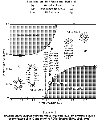
The right side of Figure 4-11, which corresponds to high SMDNS concentrations, is characterized by a separate DNAPL phase and an aqueous phase rich in surfactant micelles containing dissolved 1,2-DCE. The micelles are composed of surfactant monomers with their hydrophobic tails pointed inward. Such systems are typically referred to as Winsor Type I, or type II (-) systems. The system is analogous to the solubilization surfactant systems discussed previously in that the majority of surfactant resides in the aqueous phase, and contaminant recovery is promoted by partitioning of contaminant into surfactant micelles. This type of system has also been referred to as a single-phase microemulsion (SPME). There are two fluid phases to consider in this system (water and NAPL), but the surfactant micelles reside in only one of the phases (the water).
As the concentration of SMDNS is reduced in Figure 4-11, a separate middle phase microemulsion is formed. A microemulsion is a thermodynamically stable solution of micelles and structured aggregates of micelles. The formation of this third phase is associated with achieving ultra-low interfacial tensions. The primary recovery mechanism in such systems is clearly NAPL mobilization in response to the reduction of capillary forces. The middle phase microemulsion system is typically referred to as a Winsor Type III, or type III system. The additional phase that is formed in these systems has a density between that of water and NAPL, hence the term "middle phase."
As the concentration of SMDNS is further reduced, as shown in Figure 4-11, a separate water phase will exist in equilibrium with a NAPL phase rich in surfactant micelles containing water. The surfactant molecules comprising the micelles are oriented with their hydrophobic tail groups pointing outward toward the NAPL phase. Such systems are typically referred to as Winsor Type II, or type II (+) systems. Care must be taken to ensure that a surfactant system designed as a Winsor Type I or Winsor Type III system does not shift to a Winsor Type II system in the subsurface because of the significant loss of surfactant that will occur due to partitioning into the NAPL phase.
Figure 4-11 indicates that achieving a middle-phase microemulsion is not only a function of the concentration of surfactant added to the system, but also the salinity and temperature of the system. For ionic surfactants, a high salinity will drive surfactant monomers into the NAPL phase, promoting the formation of a Winsor Type II system, while a low salinity will promote the formation of a Winsor Type I system. While the addition of salt can drive surfactant into the NAPL phase, the addition of a cosolvent such as alcohol can result in the surfactant being more water soluble. The salinity at which a third-phase microemulsion forms is often referred to as the optimum salinity. In reality, the third phase will form over a range of salinities, but may revert to unstable mixtures at the edges of the salinity window. Baran, et al. (1994) show that this salinity window is a function of NAPL, surfactant, and electrolyte type.
Figure 4-11 indicates that high temperature and low HLB number promote the formation of a Winsor Type II system, while low temperature and high HLB promote Winsor Type I systems. The phase behavior for nonionic surfactant-based systems is especially sensitive to temperature in contrast to ionic surfactant-based systems, which are particularly sensitive to salinity. It is important that the design of a NAPL mobilization flood consider carefully the temperature and salinity of the target aquifer. In some cases, the salinity of the system can be manipulated by preflooding the aquifer with a specified electrolyte solution or by injecting salts as part of the surfactant solution. In some circumstances, it may be undesirable to inject salts into an aquifer, in which case the phase behavior needs to be manipulated through the surfactant HLB number, the use of cosurfactants, or the use of cosolvents such as water miscible alcohols (Shiau, et al., 1994).
The distribution of phases and phase compositions in a surfactant - NAPL - water system can be represented by ternary phase diagrams. Figure 4-12, for example, illustrates ternary phase diagrams for type II (-), type III, and type II (+) systems. Each apex in these diagrams represents 100 percent composition of the labeled component. The surfactant component is actually taken to represent the combination of surfactant and cosurfactant or cosolvent. The curved surface within the type II (-) and type II (+) diagrams is referred to as the miscibility envelope (or binodal curve) and represents the boundary between a completely miscible, single-phase system and a two-phase system. The two phases below the miscibility envelope are taken to be a water-rich phase and a NAPL-rich phase, with surfactant distributed between the two phases. The straight lines below the miscibility envelope provide information regarding the proportion of two phases in the system and the phase compositions. In the type II (-) system, for example, an overall system composition represented by the open circle is composed of a NAPL-rich phase occupying a/(a+b) of the system. The water-rich phase occupies b/(a+b) of the system. The composition of each phase is given by the composition of the endpoints of the tie lines (i.e., where they intersect the miscibility envelope).
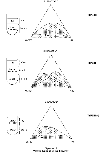
In a type II (-) system, the tie lines slope down toward the NAPL (oil) endpoint, indicating that the surfactant partitions preferentially into the water-rich phase. The water-rich phase is referred to as the microemulsion phase in Figure 4-12, consistent with the fact that this phase contains the majority of surfactant in the form of micelles. It is the type II (-) system that needs to be optimized in a solubilization surfactant flood. In the type II (+) system, the tie lines slope down toward the water endpoint, indicating that the surfactant partitions preferentially into the NAPL phase. The NAPL-rich phase is referred to as a micro-emulsion here because it contains the majority of surfactant in the form of micelles. A type II (+) system is often undesirable because the partitioning of surfactant into the NAPL represents a significant surfactant loss mechanism.
In the type III system, a third-phase microemulsion is formed for system compositions within the lower triangular region below the miscibility envelope. The third phase is referred to as a microemulsion because it represents a stable mixture of NAPL, water, and surfactant micelles. The formation of a type III system is associated with achieving ultra-low interfacial tensions between the middle-phase microemulsion and both the water and NAPL phases. Type III systems are therefore suitable for NAPL mobilization floods. The volume of contaminant per unit weight of surfactant in the middle phase is often referred to as the solubilization parameter (West and Harwell, 1992). This parameter is useful in determining the amount of both surfactant and contaminant that will be present in the recovered middle phase. This information is required for the design of a produced-fluids treatment system. Ternary-phase behavior is discussed by Lake (1989).
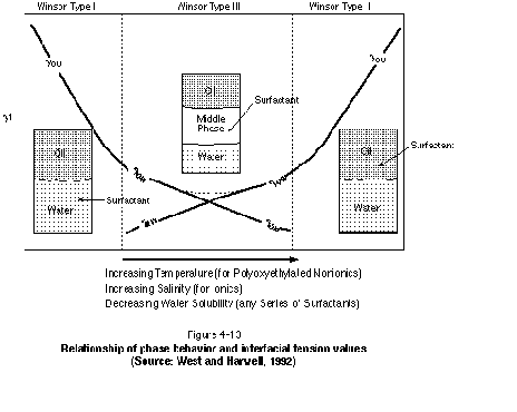
The variation of interfacial tension between Winsor Type I, Winsor Type II, and Winsor Type III systems is illustrated schematically in Figure 4-13. As shown in the figure, interfacial tensions decrease as either the Winsor Type I or Winsor Type II systems move toward the Winsor Type III system. The figure indicates that a shift from left to right on the diagram (Winsor Type I to Winsor Type II system) will occur for increasing temperature (particularly nonionic surfactants), increasing salinity (particularly anionic surfactants), and decreasing water solubility of the surfactant.
The design of a NAPL mobilization flood also can benefit from the use of a 3-parameter diagram. Such diagrams relate various system parameters and phase boundaries to each other. Figure 4-14, for example, is a three-parameter salinity scan. The diagram plots surfactantcosurfactant concentration versus NaCl concentration. The NaCl concentration is expressed as the mass of NaCl per volume of the system (NAPL and water). For a given surfactantcosurfactant concentration, the formation of a middle-phase microemulsion occurs over a specified range of NaCl concentration only. The dashed line between the two solid lines represents an equal amount of NAPL and water in the middle phase. The point at which the two solid lines intersect represents a single-phase system consisting of only a microemulsion. At this point, the solubilization parameter is maximized and the interfacial tension is zero (because there is only one phase).
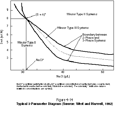
Parameters other than salinity can be varied in a three-parameter diagram. In Figure 4-14, the ratio of surfactant (S) to cosurfactant (A) is held constant, as is the water-to-NAPL ratio and the temperature. If the salinity were held constant, one of these other parameters could be varied to examine system behavior. It is clear that maintaining a middle-phase microemulsion in situ will be challenging given its sensitivity to surfactant type, surfactant concentration, surfactant-to-cosurfactant or -cosolvent ratio, salinity, and temperature. Variations in any of these parameters during a surfactant flood in response to aquifer heterogeneity, variations in sorption, and variations in NAPL saturation can drive the system to either a type II (+) or a type II (-) system, thereby bringing about failure. A simple difference in the rate at which a surfactant and cosurfactant sorb to aquifer material, for example, can bring about in situ chromatographic separation of the mixture components.
In a typical mobilization flood, a certain degree of NAPL solubilization will also occur. The degree of solubilization desired along with the mobilization can be manipulated through careful surfactant, cosolvent, and electrolyte selection. The objectives of the removal mechanism must be very clear (i.e., mobilization, solubilization, or a combination of the two) prior to embarking upon system design. Baran, et al. (1994a, 1994b) discuss phase behavior in surfactant/cosolvent - chlorinated solvent DNAPL systems.
It is worth noting that middle-phase microemulsion systems involving the injection of 5 to 10 percent of a pore volume of high-concentration surfactant solution were popular in the petroleum industry when oil prices were high. The lower oil prices of the 1980s and 1990s have practically eliminated this type of surfactant system for the petroleum industry because of the cost of the required chemicals. Recent attention is being given to low-concentration surfactant systems where ultra-low interfacial tensions are achieved without the formation of a middle-phase microemulsion. These systems can still be characterized as either type II (-) or type II (+) systems and can be represented using the ternary phase diagrams discussed above. The minimum interfacial tension in these systems is reached at the surfactant CMC, which can be lowered by the addition of salt. Some systems, for example, have shown ultra-low interfacial tensions at surfactant concentrations of less than 50 ppm. Given the relatively high cost of surfactant flooding for environmental applications and the complications associated with maintaining a middle-phase micro-emulsion in situ, the future design of NAPL mobilization floods will likely focus on the use of low-concentration surfactant/cosolvent systems that achieve ultra-low interfacial tensions without the formation of a middle-phase microemulsion.
The adsorption of surfactants to solid surfaces can lower the concentration of free surfactant in aqueous solution. Of primary concern is adsorption of surfactant to mineral surfaces. If the degree of adsorption is great, surfactant concentrations could drop below the CMC, rendering the surfactant solution with no ability to solubilize. Therefore, the amount of surfactant mass that will sorb should be accounted for when selecting injection concentrations. In addition to reducing the number of monomers available for micelle formation, adsorption will cause the surfactant velocity to be lower than the groundwater velocity. This should be taken into account when calculating travel times and sampling intervals. Also, adsorbed surfactant may need to be desorbed at the completion of a remediation effort, particularly surfactants that are toxic and are themselves a threat to groundwater quality.
In addition to adsorption to mineral surfaces, surfactant partitioning to the NAPL phase must be considered. All surfactants will have a certain solubility in NAPL, the degree of which is indicated by the HLB number. Significant partitioning of surfactant to the NAPL phase will cause a reduction in the concentration of surfactant in aqueous solution and will lead to a retardation of the surfactant velocity. An estimate of the volume of NAPL in place, and execution of a laboratory batch partitioning test prior to surfactant injection, will provide an estimate of the additional mass of surfactant that will need to be injected to account for losses to the NAPL phase.
The degree of surfactant sorption in an aqueous system depends largely on the nature of the surfactant monomer hydrophilic head group. In general, cationic surfactants have the potential for significant sorption on mineral surfaces. Anionic surfactants generally adsorb less than nonionic surfactants and much less than cationic surfactants. The degree of sorption by cationic surfactants can be so great that certain authors have proposed creating in-situ sorption zones through targeted injection of these compounds in the path of organic contaminant plumes (Hayworth and Burris, 1996; Westall, et al., 1994).
Adeel and Luthy (1995) demonstrate that Triton X-100 (a nonionic surfactant) sorption onto aquifer sediments is a rate-limited process, and that the degree of sorption is concentration dependent. The implication of this is that it may require a long period of flushing with clean water to desorb surfactants from aquifer sediments following the completion of a remediation effort. The amount of sorption that will occur at a particular site is site-specific and should be evaluated by performing laboratory column tests prior to field-scale pilot testing and full-scale implementation. Further consideration of surfactant sorption is provided by numerous authors, including Sabatini, et al. (1995); Abdul and Gibson (1991); Holsen, et al. (1991); Narkis and Ben-David (1985); Di Toro, et al. (1990); Rouse and Sabatini (1993); and Urano, et al. (1984).
Surfactant degradation, and primarily biodegradation, is of interest for a number of reasons. During active surfactant flooding, biodegradation is not desirable because it will decrease the amount of active surfactant available for NAPL removal. However, once the surfactant flood is complete, it is desirable to eliminate any remaining surfactant so that it does not persist in the subsurface environment. Biodegradability is also a factor if biological treatment of the produced fluids is planned.
Biodegradation of surfactants is a complex subject that has been studied extensively by the soap and detergent industry. Few generalities can be made regarding the biodegradability of surfactants. The surfactant supplier should be consulted on the degradability of its product. Additional laboratory studies may be needed to evaluate site-specific biodegradability. Potential laboratory studies will be discussed in Chapter 5 of this manual.
The concentration of a surfactant plays a significant role in its degradation. At high concentrations, surfactants can be very disruptive to microorganisms, even killing them. The concentration threshold depends on the type of surfactant used and the bacterial species present in the subsurface. In a surfactant flushing operation, it is quite possible that the surfactant concentrations in the "middle" of the chemical flood will be high enough to prevent significant microbial degradation. In addition, oxygen and other electron acceptors likely will be in limiting concentrations compared to the surfactant concentration, further inhibiting biodegradation. At the edge of the surfactant "front," conditions may be favorable for biodegradation to occur to a limited degree.
After a surfactant flush is complete, it is often desirable to flush the formation with water for a number of pore volumes to remove as much of the remaining surfactant and contaminant as possible. For example, 13 of the 26 projects included in Appendix A include post-treatment waterflooding. Even if the surfactant is not a risk to human health or the environment, it is preferable for any remaining surfactant to biodegrade. Most surfactants will eventually biodegrade, depending primarily on the environmental conditions in the subsurface after flushing. For example, if there is a continuous supply of oxygenated groundwater, aerobic biodegradation should occur. If, however, the oxygen supply is not adequate, anaerobic or anoxic biodegradation may take place. Anaerobic biodegradation processes are generally less "robust" than aerobic processes and are generally slower. Again, laboratory and pilot field studies may be required if the remaining surfactant is a concern.
The toxicity of the particular surfactant selected for remediation purposes must be considered during the design stage. The toxicity of surfactants to humans, micro-organisms, and various forms of aquatic life varies widely, with cationic surfactants often more toxic than anionic or nonionic surfactants. The recognition that surfactant toxicity may be a major limitation to the widespread use of this technology in shallow systems has led many researchers to investigate and employ the use of food-grade surfactants for subsurface application (Shiau, et al., 1995; Sabatini, et al., 1995).
Recently, concern has been raised in the scientific community regarding the potential for a variety of anthropogenic compounds to inadvertently mimic the biological activities of the female hormone estrogen. Certain types of estrogen, in high dosages, have been linked to cancer and other health problems. A few surfactants and their degradation products were tested for their estrogenic activity by Routledge and Sumpter (1996). None of the parent surfactants tested showed estrogenic activity. The degradation product of linear alkylbenzene sulfonates also did not show estrogenic activity. Alkylphenol polyethoxylates did degrade to persistent metabolites that were weakly estrogenic. Other research suggests that surfactants and their degradation products may have other toxicity impacts on aquatic life (Ankley and Burkhard, 1992). The potential for a surfactant or its degradation product to exhibit estrogenic activity and other toxic effects is a question that may need to be posed to the surfactant manufacturer prior to its use. There likely will be more research on the estrogenic activity of these and other compounds in the next few years.
In the context of surfactant/cosolvent flushing, a macroemulsion is an undesirable dispersion of two immiscible liquids such as NAPL and water. When one liquid is dispersed in the other, the small droplets provide a large amount of interfacial surface area, and hence greater interfacial free energy in the system. With pure liquids, the droplets may rapidly coalesce and two separate phases will form to minimize the interfacial area. Such an emulsion is unstable. The presence of a surfactant can stabilize the emulsion somewhat by reducing the interfacial tension and decreasing the rate of coalescence. In general, macroemulsions (which are different than microemulsions) are undesirable in that they can reduce the permeability of a formation through pore clogging. Emulsions are classified based on which liquid is the dispersed phase: oil in water (o/w) or water in oil (w/o). The nondispersed phase is continuous. An emulsion can be readily dispersed with the liquid of its continuous phase but is not easily diluted in the liquid of its dispersed phase. Thus, o/w emulsions can be easily diluted with water. If diluted sufficiently with the dispersed phase, the emulsion may "invert," and the dispersed phase will become the continuous phase.
The chemical nature of the surfactant, that of the dispersed and dispersing phases, and the temperature of the solution all play a role in the emulsion formation. Thus, the nature of the emulsion can change as the chemistry of the system changes. For instance, monovalent soaps tend to stabilize o/w emulsions, whereas soaps with polyvalent ions stabilize w/o emulsions. In-situ soil flushing can, in some cases, result in emulsion inversion when a sodium-based surfactant used in a soil rich in calcium causes cation exchange and release of the calcium from the soil.
In most cases of surfactant flushing, the concern is that a surfactant solution in water may form a w/o emulsion with the NAPL. These emulsions can be highly viscous and once formed are relatively immobile. Emulsions can be detrimental to the remediation process because they can trap the contaminant in a less mobile phase. As discussed, it is also possible for the emulsion to invert, in which case it will be very difficult to dilute with water. Because emulsions are inherently unstable, they will eventually collapse. However, this may require several months. Emulsions should be carefully considered in the screening stages of a system design because their formation is dependent upon a number of factors, including surfactant type and concentration, cosurfactant or cosolvent type and concentration, aquifer chemistry, and contaminant type.
Relevance
This section describes the basic functioning of alcohols in subsurface remediation systems, particularly the use of alcohol without the combined presence of surfactants. Readers familiar with cosolvent and alcohol flooding may wish to skip this section.
Key Concepts
• Alcohols are mutually miscible in both water and NAPL. Depending on the type of alcohol and the type of NAPL, alcohol will preferentially partition into one phase relative to the other. Alcohols that preferentially partition into the NAPL cause swelling of the NAPL and will reduce the NAPL density.
• When used in combination with chemical surfactants, alcohols are typically referred to as cosolvents or cosurfactants. The term cosolvent flooding, however, often refers to the injection of low-concentration alcohol solutions without the combined presence of surfactants.
• The term alcohol flooding refers to the use of very high-concentration alcohol solutions or pure alcohol only.
• Alcohols have the ability to both increase NAPL solubility in water and lower NAPL-water interfacial tension. Depending on alcohol selection and injection concentration, alcohols can be used to execute either a solubilization flood, a mobilization flood, or both.
• If enough alcohol is added to aqueous solution, NAPL-water interfacial tension can be reduced to zero, resulting in one fluid. Depending on the relative proportions of water, NAPL, and alcohol in this mixture, the resulting fluid will be either more dense or less dense than water.
• The equilibrium distribution of alcohol and number of phases occurring in an alcohol - water - NAPL system can be described by a ternary phase diagram.
• Sorption of alcohols to aquifer solids is generally not a concern. While high concentrations of alcohol may be toxic to naturally occurring organisms in groundwater, low concentrations of alcohol generally biodegrade readily in natural aquifer systems.
• As with surfactants, significant laboratory testing is required to properly match an alcohol with a NAPL type for remediation purposes.
The attractiveness of alcohol flooding as a NAPL remediation technology stems from the fact that many alcohols are mutually miscible in both water and NAPL. As a result, alcohols can increase the aqueous solubility of many sparingly soluble organic compounds. If sufficient alcohol is added to a NAPL-water system, the solubility of the NAPL can become infinite, and one fluid phase will result as the interfacial tension is reduced to zero.
As discussed in previous sections, alcohols can also be used in combination with chemical surfactants to enhance the efficiency of surfactant flooding systems. Such alcohols are often referred to as cosurfactants or cosolvents. This terminology has developed in the petroleum industry where alcohols are sometimes used to help optimize surfactant flooding systems for enhanced oil recovery. The term cosolvent flooding, however, refers to the injection of low-concentration alcohol solutions without the combined presence of surfactants. This terminology has developed in the contaminant hydrogeology community independent of the petroleum industry. The term alcohol flooding is used to describe the injection of high-concentration water - alcohol mixtures or pure alcohol only.
Table 4-3 presents the properties of various alcohols that are currently being considered for environmental application. These are low-molecular-weight alcohols that are completely soluble in water. The table also indicates that these alcohols are less dense than water. This can be an advantage in terms of upward mobilization of NAPL, but can be a disadvantage in terms of solution delivery below the watertable.
| Table 4-3 |
|||
| Physical Properties of Selected Alcohols |
|||
| Alcohol |
Density |
Viscosity |
Aqueous Solubility |
|---|---|---|---|
| Methanol |
0.791 |
0.597 |
miscible |
| Ethanol |
0.789 |
1.2 |
miscible |
| 1-Propanol |
0.804 |
2.25 |
miscible |
| 2-Propanol (IPA) |
0.785 |
2.5 |
miscible |
Source: Verschueren, 1983; Weast, 1986. |
|||
Low concentrations of alcohol have been shown to increase the aqueous solubility of many organic contaminants through what is referred to as a cosolvent effect. The term cosolvent flooding refers to the injection of low concentrations (e.g., 1 percent to 5 percent by volume) of alcohol such that the system remains a two-phase (NAPL-water) system. The degree of solubility enhancement that occurs in a cosolvent flood is not only dependent on the concentration of alcohol, but also on the specific component composition of the NAPL. In a low-concentration alcohol flood, many pore volumes of injection solution need to be flushed through the NAPL zone to achieve significant removal. Unlike with the injection of high concentrations of alcohol (70 percent to 90 percent), significant NAPL mobilization is not expected to take place.
The presence of alcohol in water also serves to reduce the amount of contaminant sorption to solid matter. Rao, et al. (1985) present the following equation to quantify the reduction in contaminant partitioning to solid matter as a function of alcohol concentration:
 (3)
(3)
where
![]() is
the partitioning coefficient for the water-alcohol system,
is
the partitioning coefficient for the water-alcohol system,
![]() is
the partitioning coefficient from water, a is an empirical constant,
sc is a parameter incorporating the hydrocarbonaceous and polar
surface area of the contaminant, and fc is the
fraction of alcohol present. Although the focus of this manual is the removal
of immiscible-phase NAPL, it is clear that low-concentration alcohol flushing
has application for the removal of sorbed organic contaminants, independent of
the presence of NAPL (this is also true for certain surfactants).
is
the partitioning coefficient from water, a is an empirical constant,
sc is a parameter incorporating the hydrocarbonaceous and polar
surface area of the contaminant, and fc is the
fraction of alcohol present. Although the focus of this manual is the removal
of immiscible-phase NAPL, it is clear that low-concentration alcohol flushing
has application for the removal of sorbed organic contaminants, independent of
the presence of NAPL (this is also true for certain surfactants).
If moderate to large amounts of alcohol are added to a NAPL-water system, the alcohol may partition into both the NAPL and water phases, bringing about significant changes to NAPL viscosity, density, solubility, and interfacial tension (Lunn and Kueper, 1996). If sufficient alcohol is added, complete solubilization of NAPL in the alcohol-water mixture can result. This is best illustrated through use of a ternary phase diagram. Figure 4-15 presents a 2-propanol (IPA) - water - PCE ternary phase diagram. For all system compositions above the binodal curve (miscibility envelope), complete miscibility exists. Below the binodal curve, a two-phase system exists with alcohol partitioned into both the water and PCE phases. The endpoints of the tie lines (where they meet the binodal curve) indicate the relative proportions of the NAPL and aqueous phases in the system, as well as the composition of each phase.
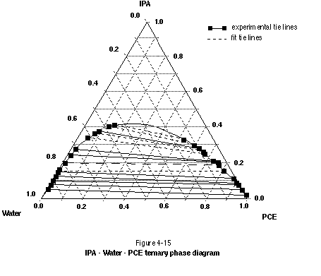
Ternary phase diagrams with tie lines sloping down toward the NAPL endpoint signify systems where the alcohol is preferentially soluble in water. If alcohol concentrations are kept below the binodal curve, the primary removal mechanism in such systems will be NAPL dissolution. This dissolution process can be subject to rate-limited mass transfer (Imhoff, et al., 1995). Some NAPL mobilization also may occur if the interfacial tension is sufficiently reduced. If alcohol concentrations are increased to above the binodal curve, the interfacial tension will be reduced to zero, resulting in complete miscibility and therefore complete mobilization of the NAPL. Whether the miscible mixture will be more or less dense than water depends on the initial density of the NAPL and the relative proportions of water, NAPL, and alcohol in the system.
Ternary phase diagrams that have tie lines sloping down toward the water endpoint signify systems where the alcohol is preferentially soluble in the NAPL. If alcohol concentrations are kept below the binodal curve, the primary removal mechanism will be NAPL mobilization in response to a reduction of interfacial tension and swelling of the NAPL phase. A certain degree of solubility enhancement also will occur. As with the system discussed in the previous paragraph, alcohol concentrations above the binodal curve lead to an interfacial tension of zero and complete miscibility. The primary removal mechanism will be mobilization (miscible extraction) of the NAPL. Whether the miscible mixture will be more or less dense than water will again depend on the initial NAPL density and the relative proportion of components in the system.
Ternary phase diagrams for various alcohol - chlorinated solvent systems are presented by a variety of authors, including Brandes (1992); Falta, et al. (1996); and Lunn and Kueper (1996, 1997). The work of Lunn and Kueper (1997) demonstrates that equilibrium ternary phase diagrams can be used successfully to predict performance in two-dimensional laboratory experiments involving single-component DNAPLs such as PCE. The work of Peters and Luthy (1993) and Luthy, et al. (1992) show that ternary phase diagrams can be used to predict performance in multicomponent systems involving creosote and coal tar. In this work, the complex composition of the NAPL was successfully represented on a ternary phase diagram as a single pseudo-component. Alcohol flushing for the removal of creosote and coal tar DNAPL is also discussed by Hayden and Van der Hoven (1996). Also, various alcohols are sometimes combined to yield an optimal chemical mixture. It may be advantageous, for example, to combine an alcohol that partitions preferentially into the NAPL phase with an alcohol that resides primarily in the aqueous phase.
Sorption of alcohol to aquifer solids is generally not of concern in remediation applications. The cosolvent effect arising from the addition of alcohol to aqueous solution brings about desorption of organic contaminants from aquifer solids, and it has been suggested as a means of enhancing pump-and-treat systems where mass removal is limited by desorption from aquifer solids. This mechanism is not the result of competition for sorption sites.
Much of the previous discussion on surfactant degradation is also true for alcohols. While high concentrations of alcohol may be toxic to subsurface microorganisms, alcohols at low concentration (less than about 1 percent) are thought to be readily biodegradable (Brusseau, et al., 1995). This is an advantage in environmental applications where high-concentration alcohol solutions may be injected to facilitate NAPL dissolution and/or mobilization. Significant losses of alcohol due to biodegradation are not expected. Low concentrations of alcohol remaining after the majority of fluid extraction has taken place may biodegrade because alcohol is so highly biodegradable at low concentrations.
The alcohols considered for cosolvent flooding are generally toxic at high concentrations. In addition, high-concentration solutions of alcohol can be flammable and explosive, requiring precautions during transportation, handling, and injection. The toxic nature of alcohols requires that care be taken to ensure that all injected fluids can be recovered from the subsurface. This typically requires a good understanding of the flow characteristics of a site. It is prudent to carry out a tracer test between injection and withdrawal wells using a nontoxic tracer prior to the injection of alcohol to ensure that injected fluids can be completely recovered.
Relevance
The effectiveness of surfactant/cosolvent flushing is based largely on the ability of injected fluids to contact regions of residual and pooled NAPL in the subsurface. This ability is characterized by the sweep efficiency. This term is used widely in the petroleum industry to characterize the effectiveness of enhanced oil recovery floods. Readers with knowledge of enhanced oil recovery operations may choose to skip this section.
Key Concepts
• Sweep efficiency relates to how uniformly an injected fluid solution contacts the intended target area of contaminants. Sweep efficiency is generally less in a highly heterogeneous aquifer.
• The mobility ratio characterizes the mobility of one phase relative to the other phase.
• A less viscous fluid displacing a more viscous fluid can lead to the formation of hydrodynamically unstable fingers, leading to bypassing of the displaced fluid and premature breakthrough of the displacing fluid.
• The mobility ratio can be manipulated by adding polymer to the injected solution. Through proper implementation, this will lead to an increase in sweep efficiency. The use of agents such as polymers to increase sweep efficiency is standard practice in the petroleum industry.
• Foams may be utilized to improve sweep efficiency by reducing the effective permeability of high-conductivity zones, thereby promoting flow into low conductivity zones that would otherwise be bypassed.
Sweep efficiency can be defined as how uniformly the injected fluid contacts the area contaminated by the NAPL. Sweep efficiency is affected by aquifer heterogeneity as well as the NAPL and displacing phase fluid characteristics. A highly heterogeneous aquifer will result in a lower sweep efficiency because the injected chemical solution will tend to migrate preferentially through the higher permeability regions. If the injected surfactantcosolvent solution can only contact 60 percent of the lenses and laminations containing NAPL, for example, 40 percent of the NAPL will be left behind in the aquifer, resulting a sweep efficiency of 60 percent.
In addition to heterogeneity, the sweep efficiency will be a function of the NAPL viscosity, and surfactant/cosolvent solution viscosity. This is best characterized by the relative mobility of each phase, which is defined as follows:
![]() (4)
(4)
where MR is the mobility ratio, µN is the nonwetting phase viscosity, krw is the relative permeability to the wetting phase, µw is the wetting phase viscosity, and krN is the relative permeability to the nonwetting phase. For most field applications, water will be wetting with respect to NAPL.
The mobility ratio defines how the displacing phase and NAPL phase move relative to each other in the porous matrix at various NAPL saturations. A mobility ratio of less than 1 indicates that the NAPL phase moves at a greater rate through the porous medium than the displacing phase. A mobility ratio greater than 1 indicates the displacing phase moves through the porous medium at a greater rate than the NAPL. A mobility ratio greater than 1 is generally undesirable because this will lead to premature bypassing of NAPL and a lowering of sweep efficiency.
The mobility ratio can be changed by altering either the viscosity or relative permeability of the fluid phases. The viscosity of the injected phase can be increased by adding polymer to the displacing phase (this is discussed further below), thereby decreasing the mobility ratio. Polymer will also adsorb onto the aquifer solids to decrease the relative permeability to the displacing phase (e.g., water). A decrease in the displacing phase mobility decreases the mobility ratio and diverts the displacing phase to areas not previously contacted. Both phenomena increase sweep efficiency.
Addition of a surfactant to the injected phase may increase the relative permeability to water and, therefore, the mobility ratio, decreasing sweep efficiency. Including a polymer with the surfactant in the displacing phase will counteract this effect. Another way to increase sweep efficiency is to inject multiple volumes of the displacing phase into the porous matrix and to chemically reduce the permeability of the high-capacity zone. It may also be beneficial to investigate the use of physical subsurface barriers such as sheet piling and slurry walls to direct a greater percentage of the injection solution to the target NAPL zone. The benefits of physical subsurface barriers can be investigated with a standard groundwater flow model. Flooding the target area in alternate directions, such as parallel to bedding followed by perpendicular to bedding, may also improve contact with individual zones of residual and pooled NAPL.
When flooding a site contaminated by LNAPL, sweep efficiency may be lowered by the presence of the capillary fringe. Injected solutions will tend to migrate below the watertable, making contact with NAPL suspended in the capillary fringe difficult. Methods to combat this include raising the watertable, and selecting an alternative technology for removal of NAPL present above the watertable. Caution should be exercised when considering the injection of surfactants/cosolvents into the unsaturated zone because of preferential flow effects and the difficulty in extracting residual fluids at the completion of the flood. Sweep efficiency is also influenced by the relative density of displacing and displaced phases. Injecting an alcohol solution that is less dense than water, for example, will result in gravity over-ride of the bottom of the target NAPL zone, thereby decreasing sweep efficiency.
Polymer can be added to an injected solution to improve sweep efficiency by increasing the viscosity of the injection water, which increases the displacing phase viscosity, decreasing the hydraulic conductivity of the soil. This will decrease viscous fingering and thereby increase sweep efficiency. A reduction in hydraulic conductivity of the higher-permeability lenses and laminations also will promote cross-flow into lower-permeability lenses, thereby decreasing the detrimental influence of heterogeneity. Including a polymer in the surfactant/cosolvent solution will improve the effectiveness of a surfactant/cosolvent flush. Pitts, et al. (1995) demonstrated that addition of a polymer will reduce the mobility ratio when polymer is included with a surfactant displacing phase.
A variety of polymer types have been evaluated for use as viscosity-increasing agents in the petroleum industry, and the following polymers are used most often:
• Xanthan gum
• Hydrolyzed polyacrylamide
• Hydroxethylcellulose
• Carboxymethylhydroxyethycellulose
• Glucan
Of these, polyacrylamide and xanthan gum are the most widely used polymers for altering a solution’s mobility ratio. Polyacrylamide is the only polymer that will increase solution viscosity and cause a significant reduction in effective water permeability. Polyacrylamide is the most prevalent polymer type used in oil field applications. The viscosity of polyacrylamides is a function of the solution chemistry. For example, increasing solution salinity, especially divalent cations, decreases the apparent viscosity of a polyacrylamide solution. While polyacrylamide is used in food, to treat drinking water, and for a variety of manufacturing processes, care must be taken to ensure it does not contain more the 0.05 percent residual acrylamide monomer, which is potentially very toxic.
Xanthan gums (biopolymers and polysaccharides), which are a fermentation product produced by a mutant of Xanthamonas campestris, are the second major class of polymers used for mobility control in the petroleum industry. Xanthan gum is a polysaccharide made from the saccharide monomer units D-glucose, D-mannose, and D-glucuronic acid. Xanthan gum is typically less impacted by solution chemistry. Historically, commercially available xanthan gums contained a substantial portion of cellular debris that was removed by diatomious earth filtration at the application site. Manufacturers now report that the debris has been enzymatically removed and injectivity loss due to cellular debris is not a problem. However, filtration as a preventative measure is prudent.
Polymer retention by soil, either through adsorption or mechanical entrapment, can be beneficial as well as detrimental to a mobility control polymer flood. Polymer retention varies with polymer type, molecular weight of the polymer, rock composition (pore size, pore size distribution, permeability), brine salinity, brine hardness, flow rate, temperature, and polymer concentration. Typically, polymer retention increases with decreasing permeability. This is because the surface area for adsorption can increase due to more but smaller capillaries, and the smaller capillary diameter can lead to more entrapment of polymer. While polymer adsorption is a factor for polyacrylamide polymers, xanthan gums do not adsorb significantly onto rock surfaces. Xanthan gums and polyacrylamides both create some mechanical entrapment.
If polymer is included with an injected solution, the following processes should be considered:
• Biodegradation -- partially hydrolyzed polyacrylamide biodegradation is negligible, while biodegradation of xanthan gum can be a significant factor.
• Mechanical degradation -- mechanical shear degradation of polyacrylamides occurs when a polymer solution is exposed to high-velocity flows or pumps.
Foams also may be used to improve sweep efficiency. Foams can be used as blocking agents to reduce fluid flow in high-permeability strata, thereby diverting flow. They also can be used as agents to deliver fluids with special properties to the NAPL-contaminated area. For example, because foams are less dense than water, they can target the hydrocarbon material above the watertable, such as an LNAPL.
Some researchers consider foam to be a "smart" fluid. It will move through a low-permeability section as a discontinuous phase separated by lamella that offer more resistance to flow than the gas itself would. Gas flows preferentially in the higher permeability regions because of the lower capillary displacement pressure. Foam is therefore preferentially generated in higher permeability regions of the subsurface. This results in a better sweep efficiency because remedial fluids are diverted into the lower-permeability regions that would otherwise be difficult to access. This tends to equalize the advance rate of a foam front in a heterogeneous medium.
An important problem that has been recognized in the oil industry is that foams are destabilized when contacted by oil. Manlowe and Radke (1988) have compiled a list of oil-destabilizing mechanisms.
Foams made from surfactant solutions can be designed to exhibit properties other than foaming and foam stability. Wyatt (1992) used foams to transport surfactant solutions to the contaminant. As with many hydrocarbons, diesel oil destabilized the foam, which then degraded, leaving the surfactant solution behind. Hirasaki (1996) is investigating using a foam both to provide mobility control and as a solubilizing agent to provide better sweep efficiency and mass transport of DNAPLs. Hirasaki (1996) also notes that because the foam is mostly a gas, less produced liquid will need to be handled and disposed.
Much of the early research on foams was conducted for oil field applications involving gas injection. In this type of enhanced oil recovery, the injected gas might be carbon dioxide or natural gas, which could miscibly displace the crude oil. Given the very adverse mobility ratio for a gas displacing an oil, reducing the mobility ratio by any means will provide a more efficient displacement process. Reducing the gas (foam) phase effective permeability or increasing the gas phase viscosity will have the same effect on the mobility ratio. Continued research is required to optimize the persistence and stability of foam.
Relevance
The use of surfactants and cosolvents will lead to a lowering of DNAPL-water interfacial tension, which may in turn lead to vertical remobilization of the DNAPL. Steps can be taken to minimize such vertical mobilization. All readers considering the use of surfactants/cosolvents for DNAPL recovery should read this section. Individuals focused on the use of surfactants/cosolvents to recover LNAPLs may choose to skip this section.
Key Concepts
• For the case of DNAPL below the watertable, any lowering of interfacial tension has the potential to vertically mobilize DNAPL pools. Even the use of solubilizing surfactants, which do not achieve ultra-low interfacial tensions, will lower interfacial tension enough to potentially mobilize DNAPL.
• Vertical pool mobilization is generally undesirable if the mobilized NAPL is transferred to below the swept region of the subsurface. Special care should be taken when implementing a surfactant/cosolvent flood above fractured rock or clay.
• The risk of downward DNAPL mobilization can be reduced and even eliminated through the use of upward hydraulic gradients. The applicability of upward gradients is largely a function of DNAPL density and geological conditions.
• If the site of interest is underlain by a very fine-grained material, such as an unfractured clay, this material may act as a sufficient capillary barrier to arrest downward DNAPL mobilization.
• Through proper surfactant/cosolvent selection, it may be possible to reduce the density of the target DNAPL to below that of water, thereby eliminating the threat of downward DNAPL mobilization.
• Care also should be taken in a surfactant/cosolvent flood to ensure that the resulting microemulsion is not more dense than water. The injected chemical solution may be difficult to recover if its density becomes greater than that of water after contact with the target NAPL.
For the case of DNAPL present below the watertable, any reduction in interfacial tension has the potential to cause downward DNAPL mobilization. Because surfactant/cosolvent flushing leads to a lowering of interfacial tension, vertical DNAPL mobilization must be considered prior to applying this technology. The experiments reported by Mason and Kueper (1996) and Longino and Kueper (1995), for example, show very clearly that vertical pool mobilization can occur with the use of solubilizing surfactants. Experiments reported by Pennel, et al. (1994) also demonstrate that residual DNAPL can be vertically remobilized upon exposure to solubilizing surfactants.
Vertical DNAPL mobilization is of greatest concern where pooled DNAPL exists. To illustrate the mechanism of vertical mobilization, consider Equation (2) from Chapter 3, which provides an estimate of the height of pooled DNAPL in a one-dimensional system at equilibrium below the watertable. Any reduction in interfacial tension will lead to downward pool mobilization if the pool exists at its maximum stable height. This is because porous media displacement pressures and fractured media entry pressures are directly proportional to interfacial tension. Not all DNAPL pools at a site will necessarily exist at their maximum stable height, however, so some reduction in interfacial tension might be afforded. Unfortunately, it is extremely difficult to determine whether or not DNAPL pools exist at their maximum stable heights.
The threat of vertical pool mobilization is particularly relevant where DNAPL pools overlie fractured rock or clay. Because the fracture porosity of clay and rock deposits is extremely small compared to typical overburden porosities, even small volumes of DNAPL mobilized down from overburden to bedrock or clay can travel large distances in the fractured medium. In a porous medium, vertical pool mobilization will not be a major concern provided that pools are mobilized down into regions already being flooded with surfactants or cosolvents. As a matter of fact, it could be argued that pool mobilization is desirable in such cases because pools would dissipate themselves largely as residual NAPL, which has a high NAPL-water surface area available for mass transfer.
Table 4-4 presents the maximum stable pool height for a variety of DNAPL types and porous media permeabilities. As can be seen, a lowering of interfacial tension results in a smaller stable pool height. Also, lower-density DNAPLs such as creosote have the potential to form very large pools, even above relatively weak capillary barriers such as medium and fine sand.
| Table 4-4 |
||||||
| Maximum Stable Pool Height for Selected Porous Media, DNAPL Types, and Interfacial Tension Values |
||||||
| Silt |
Fine Sand |
Medium Sand |
||||
|---|---|---|---|---|---|---|
| 0.035 N/m |
0.001 N/m |
0.035 N/m |
0.001 N/m |
0.035 N/m |
0.001 N/m |
|
| PCE |
0.94 m |
0.027 m |
0.50 m |
0.014 m |
0.251 m |
0.007 m |
| 1,1-DCA |
3.43 m |
0.098 m |
1.83 m |
0.052 m |
0.915 m |
0.026 m |
| Creosote |
11.7 m |
0.332 m |
6.22 m |
0.177 m |
3.11 m |
0.090 m |
| Notes: |
||||||
The above discussion is focused on vertical mobilization of the target DNAPL. Care must also be taken, however, to ensure that the injected surfactant/cosolvent solution does not become more dense than water after contact with NAPL. While the injected chemical solution may initially have a density equal to or less than that of water, the density of the aqueous solution (e.g., Winsor Type I microemulsion) may become more dense than water after contact with the NAPL. This will create difficulties in fully recovering the injected chemical solution.
The risk of vertical DNAPL mobilization can be offset by the introduction of upward groundwater flow. The magnitude of upward gradient required to offset downward DNAPL mobilization is proportional to the height of pooled DNAPL and the density difference between DNAPL and water. For chlorinated solvent DNAPLs such as TCE and PCE, the required upward gradient may be as high as 0.5 or 0.6. For creosote, which has a much lower density than most chlorinated solvent DNAPLs, the required upward gradient will be on the order of 0.05 to 0.1. Longino and Kueper (1995) present an expression to calculate the required upward gradient in a three-layer porous media system. Chown, et al. (1997) present an expression to calculate the required gradient in fractured media.
Whether or not the required upward gradient can be generated depends primarily on geological conditions. DNAPL migration in low-permeability deposits will be easiest to arrest because substantial gradients can be created in low-permeability deposits with low amounts of groundwater pumping. In more permeable deposits, it may be difficult to generate the required gradients because of the large volumes of groundwater that would need to be pumped.
At certain sites, low-permeability deposits may underlie regions of the subsurface impacted by DNAPL. An unfractured clay deposit, for example, may provide an excellent capillary barrier, even under reduced interfacial tension conditions. Care must be taken, however, to ensure that the clay deposit is not fractured. DNAPL mobilization from overburden to fractured rock or clay is particularly problematic because of the low storage capacity of such deposits. In other words, even small volumes of DNAPL mobilized downward can travel substantial distances in fractured rock or clay.
The degree of permeability variation and bedding structure within the target NAPL zone will also dictate to what degree vertical DNAPL mobilization will take place. The presence of clay or silt stringers, for example, may provide adequate capillary barriers to arrest downward DNAPL migration. It should be kept in mind, however, that while a highly heterogeneous site having horizontal bedding may prevent excessive downward DNAPL mobilization, such a site may be plagued by poor sweep efficiency. The influence of permeability variations and geological structure on chemical flood performance cannot be overemphasized. For most sites, surfactant/cosolvent selection can be carried out under controlled laboratory conditions. The ultimate performance of the chemical flood, however, will be dictated largely by geological field conditions which, unfortunately, cannot be characterized as well as specific surfactant/cosolvent interactions with the NAPL.
Vertical mobilization of DNAPL can also be minimized through proper surfactantcosolvent selection. Certain alcohols will partition preferentially into NAPL in the presence of water, bringing about NAPL swelling and an associated reduction in NAPL density. Lunn and Kueper (1996), for example, have demonstrated that the density of PCE (1620 kg/m3) can be reduced to near that of water through proper alcohol selection. Combinations of surfactants and alcohols also can be chosen to engineer both the DNAPL density and the density of the resulting microemulsion. Care must be taken when designing these systems, however, because the degree of density reduction is typically dependent on the initial ratio of DNAPL volume to surfactant/cosolvent volume. In other words, favorable density reduction may be demonstrated in the laboratory for a low DNAPL-to-surfactantcosolvent ratio, but may not be achieved in regions of the subsurface where local DNAPL saturations bring about higher DNAPL to surfactant/cosolvent volume ratios.