Ground Water Currents, September 1999, Issue No. 33
Contents
Minimal Desaturation Found during Multi-Phase Extraction of Low Permeability Soils
Hydrolysis Pyrolysis and Oxidation Used at a Creosote Site
Surfactant-Enhanced Subsurface Remediation to Remove DNAPL
Training on Permeable Reactive Barriers
Minimal Desaturation Found during Multi-Phase Extraction of Low Permeability Soils
by Ralph Baker and Dan Groher, ENSR Corp., and David Becker, U.S. Army Corps of Engineers
Multi-phase extraction (MPE) typically is used to simultaneously remediate soil and ground water, improve the recovery of ground water from moderately low permeability soils, and/or improve the performance of soil vapor extraction by controlling water table upwelling and reducing soil moisture saturation. As part of an effort to develop guidance for implementation of MPE technology, the U.S. Army Corps of Engineers (USACE) has conducted field studies on soil desaturation at sites with chlorinated hydrocarbons in soil and ground water. Although MPE generally is viewed as an enhancement of soil vapor extraction capable of dewatering saturated soils, results of the studies indicate that MPE did not dewater low permeability soils significantly. Under certain conditions, however, MPE was found to remove large amounts of contaminant mass in low permeability soils.
The effectiveness of MPE was evaluated from 1996 to 1998 at three CERCLA pilot test sites, two of which are manufacturing facilities located in geomorphologically dissimilar settings at an Army ammunition plant (AAP) in the Midwest. The third test site is a former chemical waste reclamation facility in the Northeast.
Tests at each site used a slurp tube positioned within the screened interval of a single extraction well. Vapor and liquid were suctioned via the slurp tube to an aboveground equipment/treatment system. Extraction rates of vapor and liquid were measured downstream of the vapor-liquid separator. Three to five neutron probe access tubes in the vicinity of the extraction well and a neutron moisture meter were used to profile changes in the liquid content of the formation surrounding the access tubes. Analyses of intact soil cores from the MPE target zone provided data on moisture characteristics used to indicate the degree to which an initially saturated soil sample would be dewatered at equilibrium with a given level of applied vacuum.
Significant contaminant mass was removed during these tests. At one of the AAP sites, 379 kilograms of total volatile organic compounds (VOCs) were removed as vapor, and 17 kilograms as liquid. At the second AAP site, 70 kilograms of VOCs were removed as vapor and 0.45 kilograms as liquid. The vacuum influence varied spatially to a great extent. Neutron moisture profiles measured at each of these sites exhibited small differences in liquid content before versus after MPE. For example, at one of the AAP sites, the silty clay soils had initial moisture contents (by weight) that ranged from 33 to 36 percent, depending on depth. Over the course of the 7-day pilot test, during which vacuums of 40-61 centimeters of mercury were applied, moisture contents measured only 1.5 meters from the extraction well changed by less than 1 percent. Thus, an insignificant amount of dewatering occurred during MPE, and what did occur was limited only to portions of the subsurface (higher permeability lenses or macropores).
Based on these results, USACE researchers identified three scenarios that can result from application of MPE technology:
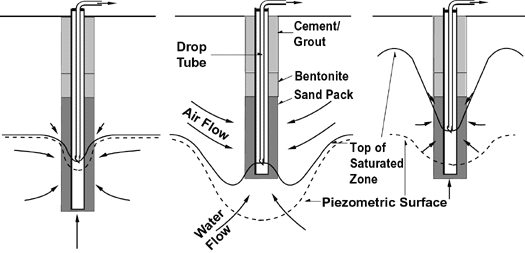
- At sites with excessively high permeability and low air-entry pressures (capillary fringe thickness less than 25 centimeters), MPE wells with slurp tubes will tend to flood with water, very little air flow will be induced, and efficiency of the process will be compromised (Figure 1, left).
- At moderately permeable locations where air-entry pressures are low (capillary fringe thickness of 25-250 centimeters), MPE should be able to enhance air flow significantly and cost-effectively (Figure 1, center).
- At sites with lower permeability soils with high air-entry pressures (capillary fringe thickness greater than 250 centimeters), MPE will not be capable of dewatering the soil. As a result, air flow will be limited to a few preferred pathways, while the bulk of the soil will remain saturated (Figure 1, right).

Figure 1. Hypothetical Scenarios during MPE
The USACE has incorporated these findings in a comprehensive MPE Engineer Manual (EM 1110-1-4010) that will be available this Fall on the Internet (http://140.194.76.129/publications/). For more information, contact Ralph Baker or Dan Groher (ENSR Corp.) at 978-635-9500, E-mail rbaker@ensr.com or dgroher@ensr.com; or David Becker (USACE Toxic and Radioactive Waste Center of Expertise) at 402-697-2655, E-mail dave.j.becker@usace.army.mil.
Hydrolysis Pyrolysis and Oxidation Used at a Creosote Site
by Roger Aines, Ph.D., and Robin Newmark, Ph.D., Lawrence Livermore National Laboratory
Since 1997, a new remediation technology involving in situ thermal oxidation through hydrous pyrolysis has removed solvent and petroleum contaminants in ground water and soil at the Visalia Pole Yard in Visalia, CA. This process effectively converts certain contaminants to benign products such as carbon dioxide, water, and chloride ions, and mobilizes other contaminants. By eliminating the need for long-term use of expensive treatment facilities, the process is proving to reduce cleanup costs at Visalia significantly. Original estimates that cleanup of this site would take approximately 120 years (using traditional pump and treat technology with enhanced bioremediation) have been reduced to only four years through the use of hydrous pyrolysis/oxidation (HPO) and other innovative technologies.
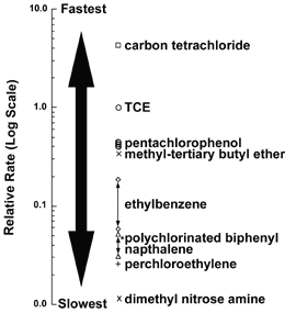
Hydrous pyrolysis/oxidation is based on the principles used in dynamic underground stripping. (See the June 1998 issue of Ground Water Currents for a related discussion.) At temperatures achieved by steam injection, organic compounds will oxidize readily over periods of days to weeks. By introducing both heat and oxygen, this process effectively has destroyed all petroleum and solvent contaminants that have been tested in the laboratory (Figure 2). The oxidation of contaminants at steam temperatures is extremely rapid (less than one week for trichloroethene (TCE) and two weeks for naphthalene) if sufficient oxygen is present. With dynamic underground stripping, the contaminants are vaporized and vacuumed out of the ground, leaving them to be destroyed elsewhere. In HPO, the dense, nonaqueous-phase liquids and dissolved contaminants are destroyed in place without surface treatment, thereby improving the rate and efficiency of remediation by rendering the hazardous materials benign by a completely in situ process. Because the subsurface is heated during the process, HPO takes advantage of the large increase in mass transfer rates (such as increased diffusion out of silty sediments) making contaminants more available for destruction.
 Results
|
At the Visalia Pole Yard, dynamic underground stripping combined with hydrous pyrolysis/oxidation uses simultaneous injection of steam and oxygen to build a heated, oxygenated zone in the subsurface. When injection is halted after the target volume reaches steam temperature (typically 2-4 weeks), the steam condenses and contaminated ground water returns to the heated zone, mixing with condensate and oxygen to destroy any dissolved contaminants. Non-aqueous phase liquid contaminants such as creosote and TCE are mobilized and recovered by pumping the treatment zone after steam condensation.
The oxidation of dissolved contaminants at steam temperatures generally occurs in less than four days if sufficient oxygen is present. Following two years of treatment, 77,111 kilograms of creosote have been oxidized in place.
Several techniques are used to monitor the underground movement of steam and rates of contaminant removal. Electrical resistance tomography is used to provide daily pictures of the steam front progress and the heated zones, thus ensuring that all soil is treated. Thermal measurements also are used. In order to verify the progress and extent of hydrous pyrolysis/oxidation, Noble-gas tracers were used to track water movement and verify that chemical reactions are occurring as expected. To evaluate the progress of chemical destruction, high-temperature systems capable of delivering a pressurized, isolated fluid stream to the surface were developed to allow for in-line analysis.
Researchers from the Lawrence Livermore National Laboratory (LLNL) responsible for development of the process estimate that large-scale cleanups with hydrous pyrolysis/oxidation at other sites could cost as little as $33 per cubic meter. For more information, contact Roger Aines (LLNL) at 925-423-7184 or E-mail aines1@llnl.gov, or Robin Newmark (LLNL) at 925-423-3644 or E-mail newmark1@llnl.gov.
Surfactant-Enhanced Subsurface Remediation to Remove DNAPL
by Laura Yea, U.S.Navy/NFESC, and Mark Hasegawa, Surbec Environmental, LLC
The U.S. Navy is conducting a pilot-scale surfactant enhanced subsurface remediation (SESR) project at Alameda Point (former Naval Air Station) located in Alameda, CA. The SESR system is designed to remove trapped dense non-aqueous phase liquids (DNAPL), primarily consisting of trichloroethane, trichloroethylene, dichloroethylene, and dichloroethane, from the soil matrix. This project is the first to demonstrate the recycling and reuse of a dual surfactant or cosurfactant system.
Injection recovery wells were installed and a tracer test was conducted prior to the SESR demonstration to confirm hydraulic capture of fluids, and to quantify the DNAPL mass existing within the 20- by 20-foot test area. The surfactant solution, which consists of 5% (by weight) Dowfax 8390, 2% AMA (food-grade biodegradable surfactants), 3% sodium chloride, and 1% calcium chloride, is flushed through the aquifer to enhance recovery of DNAPLS.
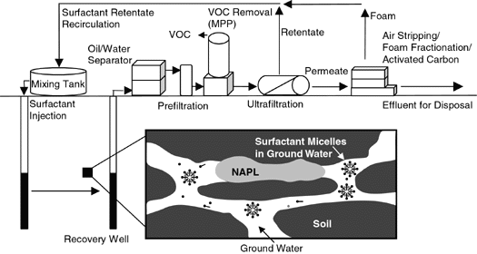
Recovered ground water is pumped through a liquid-liquid extraction unit where the NAPL constituents are removed from solution. The remaining surfactant is concentrated using physical filtration (micellar enhanced ultrafiltration) and then reinjected into the system. Reuse of the surfactant provides a significant reduction in project costs. Figure 3 provides an overview of the process.

Figure 3. Surfactant-Enhanced Subsurface Remediation
Flow
The goal of the project is to remove 95% of the trapped DNAPL from the test area within 10 days. Preliminary mass removal estimates show that up to 80 gallons of DNAPL was recovered during the test. Post test soil coring results indicate no detectable DNAPL remaining in the flushed zone. Final project results are expected to be available in October 1999.
Additional soil coring will be conducted in conjunction with post-test partitioning tracer tests to confirm the mass of DNAPL removed. For more information, contact Laura Yea (U.S. Navy/Naval Facilities Engineering Service Center) at 805-982-1660 or E-mail yehsl@nfesc.navy.mil, or Mark Hasegawa (Surbec Environmental, LLC) at 405-364-9726 or E-mail markhase@aol.com.
| Conference on
Present and Future Technology Developments The U.S. EPA will sponsor the conference Innovative Clean-Up Approaches: Investments in Technology Development, Results, & Outlook for the Future at the Indian Lakes Resort in Bloomingdale, IL, November 2-4, 1999. Stakeholders in hazardous waste site remediation projects, including EPA’s partners from other government agencies, academia, and the private sector, will have an opportunity to share the latest information on technology development, demonstration, and commercialization. Participants also will evaluate the success of past efforts and discuss future research and information needs. Workshops will be available to provide information on the SITE Program, Brownfields Program, funding sources, and electronic information resources. On-line program information, including an updated conference agenda, is available on the Internet at www.epa.gov/ttbnrmrl. |
Training on Permeable Reactive Barriers
In Situ Permeable Reactive Barriers: Application and Deployment training courses are being offered in each of EPA’s regional office areas to assist professionals in the regulatory community in overseeing the design, implementation, and monitoring of ground water remedies involving permeable reactive barriers. The U.S. EPA, Interstate Technology Regulatory Cooperation, and Remediation Technologies Development Forum jointly developed the course to meet the demand for more information on the effectiveness, cost, and general use of permeable reactive barriers.
Since June 1999, the training course has been offered in Boston, MA, Seattle, WA, and Philadelphia, PA. Future locations and dates for the course are:
- Dallas, TX, on November 16-17, 1999
- Atlanta, GA, on February 8-9, 2000
- San Francisco, CA, on March 21-22, 2000
- New York, NY, on May 2-3, 2000
- Denver, CO, on June 13-14, 2000
- Chicago, IL, on July 25-26, 2000, and
- Kansas City, MO, on September 12-13, 2000.
Participants may register for the course via the Internet at http://www.trainex.org/prb or by contacting the Southern States Energy Board at 770-242-7712.
| We now offer a new service-TechDirect-to keep you abreast of new EPA publications and event of interest to site remediation and site characterization professionals. Once a month, a TechDirect message will be sent via email describing new products and instructions on how to obtain them. |
