|
Groundwater to Surface Water
Contamination Migration Monitoring:
Trident Probe and UltraSeep Meter
> Introduction
> Trident Probe
> UltraSeep Meter
> Advantages
> Limitations
> Conclusions
> References

Introduction
The Trident Probe and the UltraSeep System were developed by the Navy and Cornell University to provide a direct measurement of groundwater discharge rates and chemical loading rates to surface water. They offer an integrated approach to quantify natural attenuation rates and human health and ecological risk.
In conducting an assessment, the Trident Probe is used first to survey potential groundwater discharge zones based on differences in conductivity and temperature. The UltraSeep System is applied next in key areas to quantify the groundwater discharge rates and contaminant concentrations.
These technologies offer a significant improvement over the use of uncertain predictions from modeling and terrestrial monitoring well results. The improved site knowledge gained from direct measurement will allow for the selection of more effective and often less expensive remedial alternatives in coastal and other surface water areas.
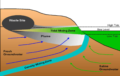
The primary driver for groundwater seepage (or migration) in near-shore environments is often the hydraulic gradient in the terrestrial aquifer. The hydraulic gradient is the pressure difference between two points caused by different water levels, which drives the flow of the groundwater; however, groundwater circulation induced by tidal stages may also contribute significantly to seepage.
In coastal areas with strong tidal fluctuations, the movement of seawater into the aquifer may create tidal mixing zones. This zone may be important in controlling the exchange of groundwater at the interface due to a process referred to as "tidal pumping." Tidal pumping occurs when seawater mixes with groundwater at high tide. As the tide recedes, the seawater and groundwater are then drawn out into the coastal waters. Because this process repeats every tidal cycle, there is potential, if the shore soils are an appropriate texture, for large volumes of groundwater to be withdrawn over time.
FIGURE 1.
Conceptual Representation of Coastal Contaminant Migration Process
and Associated Groundwater–Surface Water Interaction
Trident Probe
The Trident Probe is a multi-sensor sampling device developed to screen for groundwater discharge into surface water. The differences observed in temperature and conductivity along the bottom of a surface water body help to indicate areas where groundwater discharge may be occurring.
The Trident Probe allows large areas to be rapidly mapped to identify these areas of contrast for temperature and conductivity. The integral pore water sampler can also be used to confirm the presence of freshwater or other chemical constituents.
The major components include:
- Temperature Sensor: Temperature can be used to identify areas of groundwater seepage that may be either warmer or colder than the surface water depending on seasonal and site conditions. A digital oceanographic thermometer is used with a measurement range of -5 to +45 °C.
- Conductivity Sensor: For coastal areas, groundwater seepage is associated with low conductivity, compared to the surface water, as a result of low salinity, low clay content (high permeability), or both. For inland waters, the contrast in conductivity may not be as great with either the surface water or the groundwater having the potential for higher conductivity. The conductivity sensor has a range of 0 to 80 mS/cm.
- Pore Water Sampler: A water-sampling probe allows pore water to be extracted from the sediment at depths of up to 3 ft (90 cm) below the sediment-water interface. Pore water is collected by syringe or vacuum pump extraction. The sampling port has a small mesh (250 m) stainless steel screen.
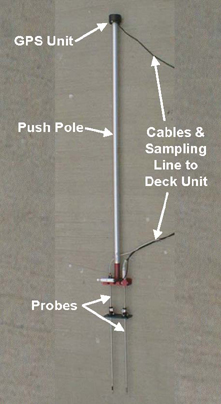
FIGURE 2.
Example of a Trident Probe
A reference conductivity and temperature sensor is also mounted on the instrument frame to provide a direct comparison (or contrast) with the overlying surface water conditions.
The Trident Probe is connected to a deck unit on the surface through a bundled cable that includes the temperature and conductivity signal wires, sampling tube, and pneumatic air-hammer hose. The deck unit includes a laptop that integrates the temperature and conductivity signals with readings from a Global Positioning System (GPS) sensor mounted on the probe.
The laptop uses a specialized software package to collect, store, and display these signals and to apply calibration and temperature corrections. The data can then be reviewed in numeric format or displayed spatially using geographic information system (GIS) software.
The spatial display capability provides for real-time evaluation of the most likely groundwater discharge areas based on temperature and conductivity contrasts.
A Trident Probe survey is conducted by inserting the probe into the bottom of the subject water body. A submersible air-hammer is provided to assist in driving the probe into the sediment.
The Trident Probe can be deployed in several ways depending on the depth of the water at the site. These methods include:
- Very Shallow (0 to 3 ft): The operator walks or wades to the sampling point and manually pushes the probe to the desired depth. Without the air-hammer, the probe can be pushed by hand to about 1 ft (30 cm).
- Shallow (2 to 40 ft): The probe is easily deployed from a small boat using an aluminum push rod, along with the air-hammer. The push rod can be lengthened in 6.6 ft (2 m) increments to a total length of about 40 ft (12 m). The boat must be well anchored to minimize lateral loading on the probe.
- Deep (40 to 60 ft): Beyond the reach of the push rod, the probe can be deployed by a diver or attached to a landing frame.
UltraSeep Meter
The UltraSeep System is an integrated seepage meter and water sampling system for quantifying discharge rates and chemical loading from groundwater to surface waters. This innovative technology combines automated sample collection with continuous flow detection. The data can be produced over a tidal cycle or other interval to show a time series of groundwater flow, contaminant concentration, and associated sensor data. This information allows a direct measurement of advective flux and contaminant concentration at a sampling point.
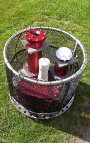
FIGURE 3.
UltraSeep System
The major components include:
- Battery: A submersible battery housing with three 12-V batteries allows the system to run continuously for up to four days.
- Funnel: A stainless steel, open-bottomed chamber to funnel the seepage water to on-board sensors.
- Water Sampler: Up to 10 seepage water samples can be collected in 1-liter sample bags. The samples are collected with a low-flow peristaltic pump in proportion to the measured discharge rate.
- On-Board Sensors: Temperature and conductivity measurements are collected by on-board sensors and stored in the data logger/control unit that also controls water sampling events.
- Ultrasonic Flow Meter: A flow meter is used to continuously measure the specific discharge or recharge in the range of approximately 1 to 1000 cm/day.
At coastal sites, a typical UltraSeep deployment runs over a 12 to 24 hour period to capture an entire semi-diurnal or diurnal tidal cycle. During this period, the seepage rate is continuously monitored and recorded by the data logger/control unit. A unique feature of the UltraSeep System is that the water samples are collected in proportion to the seepage rate, enabling the direct quantification of the chemical loading associated with the groundwater discharge.
The control unit evaluates the flow sensor signal over a five minute averaging time and determines the current seepage rate. If the seepage rate is positive, the water sampler pump is activated and the pumping rate is set at the current seepage rate. This process is repeated every five minutes and the pump flow rate is adjusted accordingly. The pump flow rates range from 0 to 13 ml/min at steps of 1 ml/min.
The control unit switches samples after the bag is full based on volume pumped and/or after a user-defined sampling interval.
The UltraSeep System is lowered to the bottom either directly from a boat or by divers using a lift-bag. Once the unit is settled on the bottom, the seal is checked by divers. A period of 2 to 3 hours is generally allowed to ensure that any response associated with the deployment activities has dissipated (e.g., sediment suspension). The control unit then initiates data logging and sample collection.
At the end of the deployment, the meter is recovered using either a lift line to the boat or diver assistance.
The UltraSeep System can be deployed in several configurations:
- Flow Only: Measures rate of discharge/recharge.
- Flow and Sensors: Measures rate of discharge/recharge; and measures temperature and conductivity.
- Flow, Sensors, and Sampling: Measures rate of discharge/recharge; measures temperature and conductivity; collects water samples to quantify contaminant concentrations.
Advantages
- Allows direct sampling at the groundwater/surface water interface.
- Allows mapping of the groundwater discharge zone.
- Allows collection of pore water and seepage water samples.
- Allows continuous measurement of discharge flow rates.
- Independent technical evaluation of the technologies is planned under the California EPA Hazardous Waste Technology Demonstration Program.
Limitations
- Trident is limited to water depths of about 40 feet for push-pole deployment.
- Conductivity contrast can be confounded by sediment characteristics (e.g., clay content).
- Temperature contrast can be confounded by other influences, such as thermoclines, direct radiation, and shading.
- Pore water collection may be limited in very fine sediments.
- Push depth into sediment may be limited by substrate.
- Trident is not amenable to rocky, rip-rap, coral or other hard bottom conditions.
- UltraSeep has a limited range of water depths from a minimum of 3.3 ft (1 m) to a maximum of 230 ft (70 m).
- Sample volume collected is limited by flow rate (low flow rates may result in insufficient volume for analysis).
- Samples may be a mixture of surface water and discharge water; funnel initially captures ~5 L of surface water and this volume must be displaced by discharge water. This factor can be corrected for in post-processing of the results.
- UltraSeep is not amenable to use in rocky, rip-rap, coral or other hard bottom conditions.
Conclusions
The Trident Probe and UltraSeep System should be considered for application at a site when:
- There is clear identification of a terrestrial contaminant plume migrating to the shoreward boundary of a surface water body.
- Applicable or relevant and appropriate requirements (ARARs) or other compliance/cleanup drivers require identification of contaminant exposure levels in the surface water or at the interface.
- Hydrogeologic modeling results are ambiguous or require field validation.
- The area where the plume is impinging needs to be clearly delineated to address risk and/or remedial options (Trident Probe).
- The rate of discharge and associated contaminant loading requires delineation to address risk and/or remedial options (UltraSeep System).
References
- Chadwick, B. 2005. Coastal Contaminant Migration Monitoring Assessment, Naval Construction Battalion Center (NCBC) Site 07, Calf Pasture Point Davisville, Rhode Island. Draft Project Report. Revision 3. January.
- Chadwick, B. and A. Hawkins. 2005. Monitoring of Water and Contaminant Migration at the Groundwater-Surface Water Interface, Demonstration Site I: Naval Support Activity Panama City. Technical Report. Final. October.
- Chadwick, B. and A. Hawkins. 2008. Monitoring of Water and Contaminant Migration at the Groundwater-Surface Water Interface (ER200422): Final Cost and Performance Report. SPAWAR Systems Center, San Diego. Technical Report 1966, 75 pp, 2008
http://www.spawar.navy.mil/sti/publications/pubs/tr/1966/tr1966cond.pdf
- Chadwick, B. et al. 2006. Evaluating transport, mass flux and attenuation at the groundwater-surface water interface. The International Conference on Remediation of Chlorinated and Recalcitrant Compounds Monterey, California May 24, 2006, PowerPoint™ presentation. http://www.clu-in.org/programs/21m2/projects/Chlor678chadwick_Small.pdf
- PSpace and Naval Warfare Center, San Diego (SPAWAR). 2003. Technical Report #1902. Coastal Contaminant Migration Monitoring: the Trident Probe and UltraSeep System, Hardware Description, Protocols, and Procedures. http://www.spawar.navy.mil/sti/publications/pubs/tr/1902/tr1902cond.pdf
|