Environmental Geophysics
Metal Detectors
The term "metal detector" (MD) generally refers to some type of electromagnetic induction instrument, although traditional magnetometers are often used to find buried metal. The disadvantage of magnetometers is that they can be used only for locating ferrous metals. MD instruments in geotechnical and hazardous-waste site investigations have several uses:
a) Location of shallow metal drums, canisters, cables, and pipes.
b) Metallic utility location.
c) Progress assessment during metal object removal and location of additional objects.
d) Avoidance of old buried metal objects during new construction, remediation, or well placement.
Basic Concept
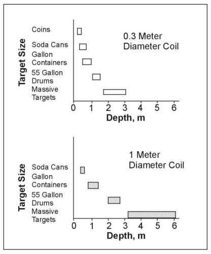
In the smaller terrain conductivity meters, the transmitter and receiver coils are rigidly connected, allowing the in-phase response to be measured in addition to the quadrature response (McNeill, 1990). Some basic equations are given in the section on Frequency-Domain EM Methods. This feature allows systems such as the EM-31 and EM-38 to function as MD's. Several coil arrangements are favored by different commercial manufacturers. The smallest units have coil diameters of as little as 0.2 m and use a vertical-axis, concentric coil arrangement. These instruments are the coin and jewelry treasure finders used on every tourist beach in the world; they have very limited depth of investigation for geotechnical targets (figure 1). One of the newest and most sophisticated MD uses three vertical-axis, 1-m2 coils: one transmitter coil, one main receiving coil coincident with the transmitter, and one focusing coil 0.4 m above the main coil. This instrument continuously records the data and has sophisticated computer software, which can yield depth of the object and other properties. In a third arrangement, the transmitter loop is horizontal, and the receiver loop is perpendicular in the vertical plane (figure 2).
Another method of classifying MD instruments is by typical application: hobby and treasure finding equipment, sensitive to very shallow and smaller surface area targets; utility-location and military instruments, sensitive to deeper and larger objects, but usually without data recording and post-processing provisions; and, specialized instruments with large coils, possibly vehicle‑mounted with continuous data recording and postprocessing.
The two most important target properties that increase the secondary field (and thus optimize detection) are increased surface area within the target mass and decreased depth of burial. Overall target mass is relatively unimportant; response is proportional to surface area cubed (Hempen and Hatheway, 1992). Signal response is proportional to depth; therefore, depths of detection rarely exceed 10 to 15 m, even for sizable conductors. Often of great importance, and unlike magnetometers, MD produces a response from nonferrous objects such as aluminum, copper, brass, or conductive foil.

Figure 1. Approximate metal detector (MD) detection depths for various targets with two coil sizes. (Benson, Glaccum, and Noel, 1983)
The main advantages of MD instruments are that both ferrous and nonferrous metals may be detected; the surface area of the target is more important that its mass; and surveys are rapid, detailed, and inexpensive. The main disadvantages are that the depth of investigation is very limited with most instruments, and metallic litter and urban noise can severely disrupt MD at some sites.

Figure 2. Block diagram of one MD coil arrangement and associated electronics. (Benson, Glaccum, and Noel, 1983)
Example Problem
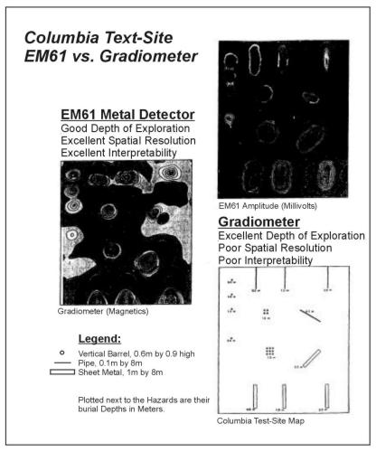
Figure 3 shows a test survey made with one of the new generation of sophisticated MD over a variety of buried metal objects and compared with a magnetic gradiometer (Geonics, 1993). Both instruments appear to have "detected" all of the buried objects, but the quality of spatial resolution is quite different. Spatial resolution is judged by how tightly the response of an instrument fits the target. The magnetometer resolves the single barrels very well. Spurious dipolar-lows become evident for the barrel clusters, and complex responses are recorded around the pipes and sheets. The MD responses fit all the targets very well, regardless of shape, orientation, or depth. This particular MD also shows the value of a second receiver coil to help distinguish between near- surface and deeper targets.

Figure 3. Test survey using a metal detector and a
magnetic gradiometer. (Geonics, 1983; copyright
permission granted by Geonics Ltd).
The pages found under Surface Methods and Borehole Methods are substantially based on a report produced by the United States Department of Transportation:
Wightman, W. E., Jalinoos, F., Sirles, P., and Hanna, K. (2003). "Application of Geophysical Methods to Highway Related Problems." Federal Highway Administration, Central Federal Lands Highway Division, Lakewood, CO, Publication No. FHWA-IF-04-021, September 2003. http://www.cflhd.gov/resources/agm/


