Environmental Geophysics
Nuclear Methods
Nuclear Magnetic Resonance (NMR) Method
Basic Concept
The Nuclear Magnetic Resonance (NMR) method is also known as the Proton Magnetic Resonance (PMR) method. NMR is a method of measuring the quantity of free water in soils and rocks. The method is based on the fact that a hydrogen proton has a magnetic moment and an angular momentum. The hydrogen atoms produce a magnetic field when they are excited by an alternating field (from a transmitter loop) in the presence of a static magnetic field (the Earth's magnetic field). In the NMR methods, three magnetic fields have to be considered:
1. The Earth's field, the amplitude of which determines the precession frequency of the protons.
2. The excitation field, produced by a current into a loop laid on the ground surface, at a frequency equal to the precession frequency (called the Larmor frequency).
3. The relaxation field produced by the protons excited by the excitation field. The amplitude of the relaxation field measured at the ground surface, after the excitation is turned off, is directly related to the number of protons that have been excited and, thus, to the water content.
Figure 1 shows the basic physics of the NMR method.
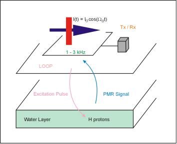
Figure 1. Schematic of the Nuclear Magnetic Resonance methods. (IRIS Instruments)
The transmitter/receiver loop provides the electromagnetic pulses that excite the protons in groundwater. These protons then decay during the transmitter current off time, and the field from this decay is detected by the same loop of wire now acting as a receiver. The data are stored in the control transmitter/receiver (Tx/Rx) box.
Data Acquisition
To our knowledge, only one company produces a commercially available NMR system, IRIS Instruments in France. This system has been used for field demonstration purposes and research and development studies. The IRIS Instruments, NMR system is called NUMIS, and the equipment consists of:
· A converter unit powered by two 12V batteries,
· A transmitter-receiver unit for pulse generation and signal measurement,
· A wire loop used both as a transmitting and a receiving antenna, and
· A portable computer for control of the system and for data recording.
The transmitter loop typically consists of a 100-m-diameter loop laid out on the ground. Other loop configurations can also be used (i.e., loop shaped like a figure 8, multi-turn 50-m loops, etc.). The excitation frequency of the transmitted pulse is typically between 1.5 and 3 kHz depending upon the amplitude of the local Earth's magnetic field. The excitation current in the loop is up to 300 amps.
Data processing consists of stacking repetitive decays at various pulse moments. To derive water content as a function of depth, measurements must be made over a range of pulse moments since the depth from which maximum signal contribution is derived increases with pulse moment. Typically, measurements are made at 16 pulse moments that may be varied from 200 ampere-milliseconds to 9,000 ampere-milliseconds. A cycle of measurements from one stack consists of the following steps:
· Charging capacitors
· Noise measurement before stack
· Current Pulse generation
· Delay time for switching from transmitter to receiver
· Signal measurement
· Data transmission
These steps require approximately 8 seconds per stack, so that measurement time for 32 stacks for 16 pulse moments requires about 75 minutes. During the acquisition process, diagnostic information is available about data quality and progress of the acquisition process.
Depending upon field conditions, a complete NMR measurement may take from 2 to 8 hours. The NMR equipment is heavy and bulky, and moving the equipment can be time consuming, especially if this is done by hand carrying. Measurement time increases proportionally with stacking times. Extremely long stacking times are sometimes needed in the vicinity of power lines.
Data Interpretation
The data mainly used in inversion and interpretation is signal amplitude as a function of pulse moment. These data contain the information about water content distribution versus depth. Inversion of the data into water content versus depth proceeds along the following steps:
- Computing the component of the magnetic field perpendicular to the local Earth's magnetic field caused by the transmitter loop, as a function of depth. This magnetic field can be computed for ground stratified in resistivity with depth.
- Computing the voltage induced in the receiver, caused by the decay of the Larmor processing component of the nuclear magnetization, after termination of the applied dynamic field. This computation for different pulse moments contains the water distribution in the ground.
- Output from the NMR inversion is a one-dimensional layered earth graphical presentation of water content (in percent) versus depth. The number of layers in the inversion can be specified or a smooth model interpretation can be selected. The inversion also derives a decay time for each layer. The decay time is an indicator of the average pore size.
An example of the field data and their interpretation is shown in figure 2.
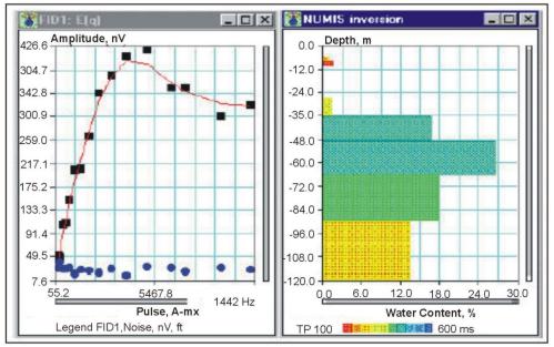
Figure 2. Field data and interpretation of a Nuclear Magnetic Resonance survey. (IRIS Instruments)
Figure 2 shows the field data from a sounding along with the interpretation. The field data curve (left plot) shows the noise level (blue circles), the measured field data (black squares), and the interpretation fit (red). The right hand graph shows the interpretation, presenting a plot of porosity vs. depth. Since water within the rock pores is required for the method to work, this plot shows the water content of the rock layers.
Depth of Penetration and Resolution of Method
The maximum depth of penetration of NMR measurements is typically about 100 to 150 m depending upon ambient noise and water content. Lateral resolution is on the order of the loop size (100 m) or better. Vertical resolution is dependent upon the product of the water content and thickness of the water-bearing layer.
Numerical modeling reveals that, for a 100-m circular antenna, a one-m-thick layer of water (water content 100%) can be detected down to 120 m when the geomagnetic field is vertical and only 100 m when it is horizontal. The layers can be discriminated down to a maximum depth of about 70 m in the case of a horizontal field and 60 m in the case of a vertical field.
Limitations
The NMR method is extremely susceptible to electrical noise from nearby power lines. Typical NMR signals are at the nanovolt level, and as mentioned above, to derive this signal in the presence of high ambient electrical noise may require up to 8 hours, or may not be possible. The NMR signal is proportional to the ambient (static) magnetic field. Thus, it is not possible to boost the signal from the groundwater protons by increasing transmitter power. In geologic environments with a high percentage of magnetic minerals, the signal from the groundwater can be screened out. In these cases, NMR measurements will not work. NMR soundings have a maximum exploration depth of about 100 to 150 m with present equipment.
The pages found under Surface Methods and Borehole Methods are substantially based on a report produced by the United States Department of Transportation:
Wightman, W. E., Jalinoos, F., Sirles, P., and Hanna, K. (2003). "Application of Geophysical Methods to Highway Related Problems." Federal Highway Administration, Central Federal Lands Highway Division, Lakewood, CO, Publication No. FHWA-IF-04-021, September 2003. http://www.cflhd.gov/resources/agm/
