 A newsletter that provides descriptions and
performance data for innovative source control technologies that have been
applied in the field.
A newsletter that provides descriptions and
performance data for innovative source control technologies that have been
applied in the field.
|
February 1999 Innovative Freeze Barrier Installation at ORNLby Elizabeth Phillips, U.S. Department of Energy, and Michael Harper, Bechtel Jacobs Co. LLC Demonstration of an innovative frozen soil barrier technology for containment of subsurface radioactive contaminants was conducted at Oak Ridge National Laboratory (ORNL) in Oak Ridge, TN, from September 1996 through September 1998. Ground water monitoring and dye tracer results indicate that the frozen soil barrier hydraulically isolates a hazardous waste area from the surrounding area. Frozen soil barrier technology for containment of subsurface contaminants consists of installing subsurface heat transfer devices around a contaminant source to freeze soil pore water, which creates a frozen soil boundary that is impervious to ground water movement. The frozen soil barrier isolates the contaminant source from the surrounding ground water, preventing transport of contaminants to adjacent areas. The barrier is maintained in situ until the source of contamination is physically removed, treated, decayed to acceptable levels, or otherwise remediated. At that point, the system is powered down and the frozen barrier eventually thaws. If the barrier is removed prior to remediation, the site will return to its pre-barrier configuration, as will the mechanism of contaminant transport from the source. The technology demonstrated at ORNL involves the installation of thermoprobes, which are subsurface heat removal devices. A conventional thermoprobe used in cold climates removes heat from soil by virtue of being a thermosyphon, using a two-phase working fluid to remove heat passively without the need for an external power supply. In contrast, an innovative “hybrid thermoprobe” technology was developed by Arctic Foundations, Inc., for use in the warmer climate at ORNL. The technology operates in a closed, two-phase system that operates in a passive-active mode requiring external power for part of the heat removal cycle. The hybrid system consists of multiple thermoprobes, each containing a two-phase passive refrigerant (carbon dioxide), a conventional refrigeration unit (using R-404A refrigerant), an interconnecting piping system, and a temperature monitoring and control system (Figure 1). Once installed around a source of contamination, the array of thermoprobes is connected to the refrigeration system by a distributive manifold. Liquid-to-gas phase change of the passive refrigerant within each thermoprobe removes heat from the surrounding soil. The conventional refrigeration portion of the system then functions to remove heat from each thermoprobe, via internal heat exchangers, for dissipation to the atmosphere. When the soil matrix adjacent to the thermoprobes reaches 0°C, soil particles are bonded together as soil moisture freezes. Additional cooling is applied until the frozen region around each thermoprobe begins to expand and build outward, coalescing with frozen regions developing around the other thermoprobes until an impermeable frozen soil barrier is formed.
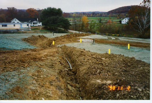
The ORNL demonstration site consisted of an unlined, backfilled, and capped earthen impoundment used from 1958 through 1961 for retention of liquid radioactive wastes generated from operation of an experimental nuclear reactor. 1984 data analysis estimated that the impoundment contained approximately 75 Curies (Ci) of 90Strontium and 15 Ci of 137Cesium in the buried sediments. In the ORNL hybrid thermoprobe system, a total of 50 thermoprobes were placed on six-foot centers around the impoundment. Each thermoprobe freezes a column with a six-foot radius, thus creating a barrier twelve feet thick. The frozen barrier wall around the impoundment was established during a “freeze-down” period of approximately 18 weeks. The frozen zone ranges from grade to a depth of 30 feet (the entire subsurface length of the thermoprobe) or more below grade around the original 75 by 80-foot perimeter of the impoundment. With the exception of a one-time anomaly attributed to a temporary reverse gradient of ground water in a former sump pump line, ground water movement through the barrier has not been detected. The project cost approximately $1,809,000, including design, installation, startup, system operation, engineering oversight, site infrastructure upgrades, and pre- and post-barrier verification studies. The system requires approximately 288 kilowatt-hours of electrical power per day for maintaining the frozen soil barrier, costing approximately $15 per day at ORNL rates. Although the demonstration is complete, the barrier will be maintained for several years until a final remediation decision is made and implemented. Complete results of the demonstration will be published through EPA’s Superfund Innovative Technology Evaluation (SITE) Program. For additional information, contact Elizabeth Phillips (U.S. Department of Energy) at 423-241-6172 or E-mail phillipsec@oro.doe.gov, or Michael Harper (Bechtel Jacobs Co. LLC) at 423-574-7299 or E-mail harperma@bechteljacobs.org. Evaluation of Alternative Earthen Landfill Coversby Steven Rock, U.S. EPA National Risk Management Research Laboratory, and Bill Albright, Desert Research Institute A new program is underway to develop basic design guidance and numerical tools for site owners, design engineers, and regulators in evaluating the performance of alternative earthen landfill covers. The Alternative Cover Assessment Program (ACAP)—a cooperative partnership of industry, government, and research institutions organized under the Remediation Technologies Development Forum’s Phytoremediation Action Team—will be implemented in four phases at 10 active disposal sites across the country in an effort to evaluate evapotranspiration and capillary break systems. Phase I ACAP activities, which began in March 1998, consist of an initial review of current data collection efforts and numerical modeling capabilities. In Phase II, the design, construction, and operation of a network of 10 cover testing facilities will occur. Phase III will combine Phase II field results with improved numerical models to predict the long-term (over 500 years) performance of alternative cover systems at the selected cover testing sites. Performance predictions will be made for a wide range of expected climatic, geologic, geographic, and hydrologic variables. The final phase, which is expected to begin in early 2003, will involve development of comprehensive guidance documentation on alternative cover systems. Resulting data will be accessible to federal and state agencies for evaluating alternative covers for specific applications. The process of selecting sites at which to construct the ACAP testing facilities is underway. Facilities will be located at, or near, disposal sites with differing geology and climates. Site characterization at each location will involve collection of local data on:
At each location, one or more full-scale (in depth) cover designs will be constructed in 200 m2 water-balance lysimeters. Vadose zone monitoring and biological and climatological observations will provide data concerning the movement of soil moisture, local climate conditions, and plant community activities. Figure 2 illustrates the anticipated design of each monitoring station.
Field efforts will focus on directly measuring the performance of the tested covers and movement of ground water through the various cover designs. All sites will be monitored through uniform methods using similar technologies. Climatic parameters used for performance testing will include wind speed and direction, air temperature, precipitation, solar radiation, humidity, and snowfall/snowpack. Plant-related parameters will include minirhizotron sampling (photographic imaging through transparent tubes inserted into the soil) of root distribution, a leaf area index, and plant biomass. Soil parameters will include:
The ACAP is expected to result in cost-effective alternative cover designs for the study sites, while providing guidelines and criteria for the development of designs at other disposal sites. Additionally, the project will help to improve numerical predictions for landfill cover performance and the technologies available for landfill cover performance monitoring. ACAP members will meet in San Francisco, CA, March 22-23, 1999, to discuss the program. Contact Kelly Madalinski (U.S. EPA, Technology Innovation Office) at 703-603-9901 or E-mail madalinski.kelly@epa.gov for more information. Mini-Cap for Landfill Cover Monitoringby Thomas Bloom, U.S. EPA, Region 5 The U.S. EPA, U.S. Army Corps of Engineers, and Ohio Environmental Protection Agency have implemented a simple and innovative way to test the permeability of a geosynthetic clay cap and associated cap components years after construction completion. This method, which has been employed since September 1998 at the Fultz Landfill in Byesville, OH, involves the construction of a miniature geosynthetic clay composite cap identical with and adjacent to the full-scale landfill cover. In addition to permeability testing, the mini-cap provides for evaluation of the long-term effects of freezing and thawing conditions as they relate to the hydraulic conductivity of the cover system. This approach is an inexpensive (less than $10,000) alternative to digging up sections of expensive cover systems when performance evaluation is needed.
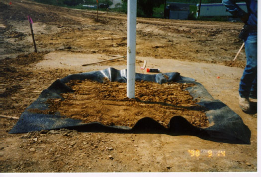
Although a mini-cap can be implemented at any time during remedial activities, plans for implementing a mini-cap at the Fultz Landfill were incorporated during the early design phase of remediation. In order to gain a complete understanding of site condition changes over time, the mini-cap was constructed simultaneous to the construction of the cover system. A single lysimeter consisting of a separate and complete 25 by 20-foot cap section was installed above the frostline, outside the area to be covered. A 4-foot stand pipe is included in the lysimeter for use in monitoring permeability, and a pan was installed to collect water that has leaked through the cover components over a certain period of time. A small piece of the mini-cap can be extracted by drilling and examined to identify any cap damage or impacts from freeze/thaw cycles. December 1, 1998, testing of the mini-cap indicated that no leakage has taken place.
In addition to providing a tool for as-needed testing of the landfill cover performance, regulators anticipate that the lysimeter will contribute significantly to evaluating the effectiveness of the full-scale landfill cover during the site’s post-closure care, such as five-year review. Contact Thomas Bloom (U.S. EPA, Region 5) at 312-886-1967 or E-mail bloom.thomas@epa.gov, or Raj Rajaram (Tetra Tech) at 847-818-7189 or E-mail rajarar@ttemi.com for more information. PRB Training CourseIn Situ Permeable Reactive Barriers: Application and Deployment is a new course that will be offered in or near the 10 cities where EPA’s regional offices are located. The course is designed to assist regulatory professionals in overseeing the design, implementation, and monitoring of ground-water remedies involving permeable reactive barriers (PRBs), and to consolidate the numerous efforts that have provided design and regulatory guidance on PRB deployment. Although geared toward state and federal regulators, industry representatives and consultants are encouraged to attend. The Remediation Technologies Development Forum (RTDF) PRB Action Team, Interstate Technology Regulatory Cooperation (ITRC) Permeable Barriers Working Group, U.S. EPA Technology Innovation Office, and U.S. EPA National Risk Management Research Laboratory partnered in development of the course. During 1999, the course will be offered in Boston, MA, on June 22-23; Seattle, WA, on August 10-11; Philadelphia, PA, on September 21-22; and Dallas, TX, on November 16-17. Details about the course and registration will be posted on the PRB Action Team home page of the RTDF Web site (www.rtdf.org/barriers.htm) as they become available. |
|
|
|