|
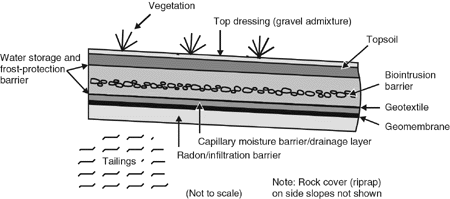
May 2000 Six-Phase Heating and Radio Frequency Heating Used at Fort Wainwrightby Therese Deardorf, U.S. Army Corps of Engineers A recent treatability study conducted by the U.S. Army Corps of Engineers at Fort Wainwright, AK, shows that radio frequency heating and six-phase heating can effectively enhance soil vapor extraction/air sparging (SVE/AS) in cold climates. In addition to quantifying the extent to which soil heating can increase volatilization and biodegradation rates during SVE and AS, the study served as a trial for determining the effectiveness of different heating techniques and identified the cost-effectiveness of soil heating. Three independent study sites were established: an unheated SVE/AS area, an SVE/AS area with radio frequency heating, and an SVE/AS area with six-phase heating. In situ monitoring sensors to measure oxygen, pressure, soil moisture, and temperature were installed at each site, and data were recorded twice daily by data loggers. Soil samples were collected before heating, at the end of moderate heating, and at the end of high-temperature heating. Both radio frequency heating and six-phase heating systems were evaluated on the basis of their capability to heat a column of soil 40 feet in diameter and 6-18 feet below grade. Both systems were found capable of heating soils at this site to moderate temperatures. During moderate radio frequency heating, soil temperatures reached 15-40°C. It is estimated that this system is capable of heating a soil column up to 60 feet in diameter under full-scale application. The delivery of radio frequency heat from a single generator and splitter system to the four antennae used in this study resulted in non-uniform soil temperatures. More uniform temperatures likely would be achieved through the use of an independent power control for each antenna. During moderate six-phase heating, soil temperatures reached 20-25°C. It is estimated that a soil column up to 85 feet in diameter could be heated under full-scale application. High-temperature six-phase heating resulted in soil temperatures that varied with radial distances from the heating electrodes. Temperatures of 100°C were reached within an 8- to 10-foot radial distance from the electrodes, while they averaged 85°C (to a depth of 6-16 feet) within a 50-foot diameter soil column. Analysis of the oxygen uptake data, soil sampling, and SVE offgas samples indicated that the SVE/AS technologies used at this site were enhanced through soil heating. At temperatures of 20-30°C, biodegradation rates averaged 2.4 mg/kg/day, a 4- to 5-fold increase over ambient rates at temperatures of less than 5°C. At the end of moderate heating, the average concentrations of gasoline-range organics in soil decreased by 55 percent in the radio frequency heating area and by 63 percent in the six-phase heating area. By the study’s conclusion, more than 70,000 pounds of volatile organic compounds had been removed by the SVE systems. Overall, this treatability study found that soil heating is cost-effective when remediating compounds with low volatility and where biodegradation is the primary treatment mechanism. Additionally, six-phase heating was found to be more cost-effective than radio frequency heating in large areas due to its lower equipment costs and ability to treat a larger area at one time. For more information, contact Therese Deardorf (USACE) at 907-384-2716 or e-mail deardorf@richardson-emh2.army.mil, or Mark Wallace (USACE) at 907-753-5660 or e-mail wallace@richardson-emh2.army.mil. Expansive Cover Installed by DOE to Contain Mixed Wastes in Eastern Utahby Joel Berwick, U.S. Department of Energy/Grand Junction Project Office, Timothy Meiers, MACTEC-ERS, and Jody Waugh, Ph.D., Roy F. Weston, Inc. Originally built in 1942 to provide vanadium for World War II, and later modified to process uranium, the Monticello mill in Utah produced extensive deposits of radioactive tailings until its closure in the early 1960s. Over the past year, the U.S. Department of Energy/Grand Junction Project Office (DOE/GJPO), the State of Utah Department of Environmental Quality, and Region 8 of the U.S. Environmental Protection Agency (EPA) have collaborated in the construction of a cover to contain 2.5 million cubic yards of radioactive material removed from the Monticello mill Superfund site. The large, multilayered cover combines fundamental ecological principles with engineered barriers that are required under existing regulatory guidelines. Ground-water recharge is limited naturally at Monticello, where thick loess soils store precipitation until evaporation and plant transpiration (evapo-transpiration) seasonally return it to the atmosphere, thereby maintaining unsaturated conditions in the subsoil. The cover design mimics and enhances this natural water balance. A capillary barrier underlying a thick soil “sponge” enhances water storage and prevents downward unsaturated flow. The cover also is designed to control radon flux, biointrusion, and erosion, and to protect critical layer interfaces from frost. Preliminary studies of natural analogs suggest that cover performance may improve over the 1000-year design life, even with expected climatic change, ecological succession, and pedogenesis. The 0.5- by 1.0-mile cover consists of the following distinct layers, from bottom to top as shown in Figure 1:
The DOE/GJPO is collaborating with EPA/Region 8’s Alternative Cover Assessment Program (ACAP) and DOE’s Office of Science and Technology on a suite of five-year studies on water balance or evapotranspiration covers at Monticello. This site is one of twelve nationwide that ACAP is monitoring to acquire the necessary field data for revising and simplifying EPA guidance on designing hazardous waste landfills. [See the February 1999 issue of Tech Trends for additional information on ACAP.] The ACAP test at Monticello uses three types of lysimeters.
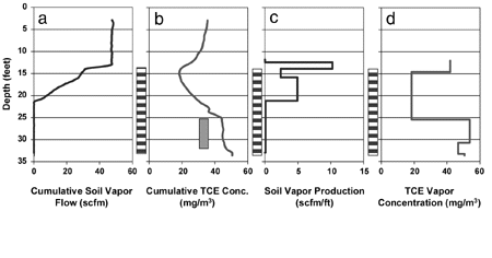
The cover’s monitoring system has produced preliminary data indicating that no release of radioactive or hazardous waste to the surrounding soil and ground water areas has occurred. Under DOE’s Long-Term Surveillance and Maintenance Program, the Monticello repository cell will be monitored annually, and the cover and adjacent areas will be assessed for damage and erosion on a quarterly basis. Vegetation on the cover, which will be protected by a wildlife fence for a minimum of five years, is expected to be fully established within two to three years. In addition, a nearby triple-lined pond with leak-detection capability will collect drainage from the tailings for 5-20 years. For additional information, contact Tim Meirs, MACTECH-ERS at 435-587-4061 or e-mail tmeirs@doejgpo.com. Pneulog Technology Used by Air Force to Optimize SVEby Jim Cummings, U.S. EPA/Technology Innovation Office, and Lloyd Stewart, Ph.D., Praxis Environmental Tech., Inc. The U.S. Air Force and the U.S. EPA’s Technology Innovation Office have collaborated on the initial deployment of a new tool to reduce long-term operational costs and accelerate cleanup through the optimization of soil vapor extraction (SVE) systems in unsaturated zones. This technology, known as PneuLog™ uses in-well instrumentation to measure air permeability and contamination production continuously along a well screen during vapor extraction. This approach to testing involves the definition of soil heterogeneity in individual wells to identify mass transfer constraints in the vadose zone. Data from several wells then are used to optimize a remedial strategy and estimate operation times for meeting closure requirements. This technology also has been used for initial site characterization, resulting in the rapid deployment of an SVE system that targets contaminant-producing soil layers and minimizes wasteful collection and treatment of clean soil gas. In contrast, conventional SVE design and optimization procedures typically rely on empirical data because field mass transfer constraints (which are capable of limiting remediation) are not quantified. As a result, conventional systems may be overbuilt, inefficient, and expensive to operate. The PneuLog approach incorporates short-term soil vapor extraction with pneumatic well logging to delineate the horizontal and vertical extent of contaminants and to quantify vertical profiles of air permeability. These data sets are coupled with extraction tests and historical data to produce a scientific basis for SVE optimization. Test equipment consists of downhole instrumentation attached to a cable that is raised or lowered by a motorized reel. Electrical leads connect the flow and contaminant sensors to a data acquisition system on the ground surface, and a photoionization detector (PID) provides a continuous reading of total contamination along the well screen. Soil air samples are collected for gas chromatographic analysis to determine compound-specific concentrations and to calibrate the PID readings. Associated above-ground software displays the cumulative airflow and total contaminant concentration as functions of depth in real time. Results from a typical pneumatic log (Figure 2) performed in Sacramento, CA, represent the type of information that may be obtained from Pneulog testing. At this site, the well was screened 12-32 feet below ground surface (bgs), and a vacuum of 17 inches of water was applied to the well. The resulting air extraction rate was approximately 40 standard cubic feet per minute (scfm). In Figure 2, a and b illustrate the raw cumulative data, while c and d indicate corresponding air production and estimated contaminant (trichloroethylene [TCE]) concentrations within the production zones.
These results suggest that the contaminants extend beyond the screen interval and within low air production zones (Figure 2d). In addition, two significant air flow zones located at 12-14 feet bgs and 16-21 feet bgs were identified; these zones correspond to coarse material (sandy gravel) observed during drilling. Test data also indicate that the highest contaminant concentrations are located in the unproductive silt and in the soils above the top of the screen. Contaminants are extracted from this well, therefore, primarily via diffusion from the silt into the overlying gravel and by advection in soils at the top of the screen. The PneuLog test is repeatable, and multiple deployments can track cleanup progress closely. When performed in a number of wells, this approach provides a more complete and accurate site characterization and conceptual model for design or optimization of SVE systems. In addition, detailed fate and transport models can be coupled with measurements of soil permeability and contaminant source characteristics to provide estimates for cleanup time. For more information, contact Jim Cummings (EPA/Technology Innovation Office) at 703-603-7197 or e-mail cummings.james@epa.gov, or Dr. Lloyd Stewart (Praxis Environmental Tech., Inc.) at 877-763-8564 or e-mail PneuLog@Praxis-Enviro.com. Joint Technical Remediation Seminars to be Held in JuneEPA’s Technology Innovation Office (TIO) and the Ground Water Remediation Technologies Analysis Center (GWRTAC) will present back-to-back, one-day seminars on June 6-7, 2000 at the Radisson Boston Hotel in Boston, MA.
For further information, visit TIO’s Web site at www.clu-in.org or GWRTAC’s Web site at www.gwrtac.org. To register for either or both of these seminars, contact Karen Devlin (Philip Services) at 215-643-5466 or e-mail kdevlin@philipinc.com.
|
|
|


