![]() A newsletter about soil, sediment, and groundwater characterization and remediation technologies
A newsletter about soil, sediment, and groundwater characterization and remediation technologies
This issue of Technology News and Trends describes selected field applications of new materials, advanced equipment, and various material dispersion methods for treating contaminated soil and groundwater.
Argonne National Laboratory Examines an Integrated Carbon and ZVI Source for In Situ Chemical Reduction
CLU-IN Resources
The Nanotechnology issue area of CLU-IN lists resources on field results, potential applications, and human health or environmental considerations concerning the use of nanoscale particles and materials for site remediation. Learn more or suggest additional resources through: www.clu-in.org/issues.
The U.S. Department of Energy's Argonne National Laboratory initiated a field study in late 2007 at a former grain storage facility near Centralia, KS, to evaluate the efficacy of combining carbon and micro-scale zero valent iron (ZVI) filings in a single injection material to achieve in situ chemical reduction (ISCR) of volatile organic compounds (VOCs). The study examined the material's ability to remediate subsurface soil and a shallow groundwater plume hotspot, the impacts of heterogenous geology on treatment, and optimal methods for delivering the carbon/ZVI material. Concentrations of carbon tetrachloride (CT), as the primary contaminant of concern, have decreased more than 99% in groundwater within most of the study area as a result of ISCR treatment.
The U.S. Department of Agriculture's Commodity Credit Corporation (USDA/CCC) used CT as grain fumigant at this facility from 1949 until 1971, when the facility was decommissioned. Elevated CT concentrations were discovered during Argonne's 2002-2004 site investigation, which was triggered by detection of CT at a local private well by the Kansas Department of Health and Environment as part of the USDA/CCC Private Well Sampling Program. Argonne's site investigation and 2005-2006 monitoring, on behalf of USDA/CCC, revealed CT concentrations of 202-219 µg/kg in source-area vadose zone soil at depths of 30-40 feet below ground surface (bgs) and 221-1,138 µg/L in three groundwater hotspots in and near the source area. The groundwater plume is restricted to a single, vertically and laterally heterogenous shallow aquifer located 40-60 feet bgs and with a groundwater flow averaging less than 0.06 ft/day.
A 45- by 75-foot treatment area was established in the vicinity of the hot spot with highest CT concentrations, and 15 injection points were installed across the area at 15-foot spacing. To establish a pre-injection baseline, vertical-profile soil coring and VOC sampling were conducted at 4- to 40-foot depths in four locations of the test area. Soil sampling indicated CT concentrations exceeded 100 µg/kg at two locations in close proximity within an upgradient corner of the test area. Baseline groundwater sampling was conducted at nine locations within and surrounding the target test area.
Sampling results indicated that CT was heterogeneously distributed with concentrations ranging from 16 µg/L to 1,285 µg/L within the proposed test area. In addition, a high concentration of CT (up to 2,646 µg/L) was identified in an area downgradient of the proposed injection locations. The injection points were adjusted accordingly to maximize coverage of CT contaminated zones. Baseline concentrations of chloroform (CF), as a byproduct of CT degradation, were generally less than 104 µg/L. A high ratio of CF to CT was assumed to indicate CT reductive degradation processes.
Injections were performed from November 26 through December 5, 2007, using a direct-push rig to achieve a minimum pressure of 300 psi. To reach different areas of the treatment zone, the carbon and ZVI were administered in two forms: (1) a fine-grained solid slurry; and (2) a liquid formulated as aqueous solution containing soluble food-grade organic carbon and dissolved iron.
To treat vadose zone soil at depths of 20 to 40 feet bgs, the carbon and ZVI material was injected as a fluid at seven injection points. A total of 3,650 pounds of liquid material diluted with water (at a ratio of 11:89) was delivered. At these seven points, a total mass of 1,300 pounds of the solid carbon/ZVI was administered as thin slurry (14%) to reach depths of 40-50 feet bgs.
Delivery of the material in both liquid and solid forms helped assure sufficient distribution in a vadose zone target area encompassing approximately 18,000 ft3 of low permeability soil. The saturated zone was treated through injection of a thicker 20% carbon/ZVI slurry targeting approximately 67,500 ft3; a total of 5,300 pounds of carbon/ZVI was injected at 14 points to depths of 50-60 feet.
Injected fluid emergence with no apparent pattern was observed at ground surface and in pre-existing borings at distances ranging from less than 1 foot to more than 25 feet from the source injection point. This daylighting indicated probable movement of the fluids/slurry along preferred vertical and lateral migration pathways within the subsurface, indicating heterogeneous lithologic conditions that could possibly limit uniform delivery.
To validate injection, direct-push soil coring was conducted within two weeks after the last injection. Continuous cores were collected to depths of 2-60 feet bgs at 3, 5, and 11 feet from the injection point with the highest CT concentrations in soil prior to treatment. Residual carbon/ZVI slurry was observed in some core intervals.
To further evaluate reductive reaction in vadose zone soil, vertical-profile soil sampling for VOC analysis was conducted nine months later at 2-foot intervals adjacent to the pre-injection, vertical-profile sampling location with the highest pre-injection concentration in soil. The results demonstrated almost complete removal of CT in the top 33 feet of vadose zone soil, where concentrations had declined from 219 µg/kg to below 6.3 µg/kg. In the remaining lower 7 feet of the vadose zone, near or in the capillary zone above the shallow aquifer, CT had decreased from 122 µg/kg to less than 62 µg/kg.
Early post-injection groundwater sampling was conducted at nine additional monitoring wells installed shortly thereafter. Sample results showed a 96-99% reduction in CT concentrations in the treatment area within one month of the injections, with the exception of two wells at the edge of the treatment area. A 20-70% reduction was observed at most sampling points within 90 feet of the 45- by 75-foot test area.
Changes in dissolved oxygen (DO) and oxidation reduction potential (ORP) in most of the treatment area over time indicted that ISCR by way of the carbon/ZVI injections produced extremely reducing, oxygen-depleted conditions in groundwater. Within one month after the injections, DO levels decreased from a pre-injection concentration of 2.9-83 mg/L to below 1 mg/L and ORP decreased from approximately -70 mV to less than -500 mV. A less reduced environment in one portion of the test area, with DO levels greater than 1 mg/L and ORP of -189 to -222 mV, may be attributed to the presence of a pre-existing well that provided preferential conduits for the injection fluids, consequently interfering with localized distribution of the injected material.
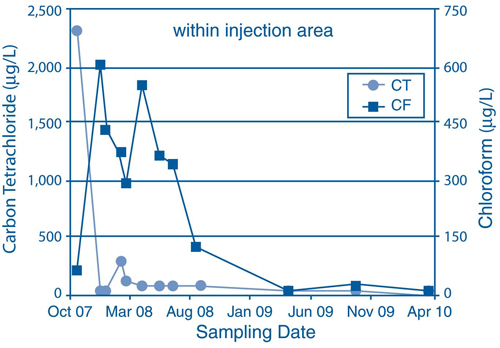
Test-area groundwater monitoring for VOCs was conducted at quarterly intervals until 2008 and semi-annually thereafter. CT transformation appeared to occur most quickly in the initial period of reductive reaction and was followed by gradual decline of accumulated CF (Figure 1). Consistent results at all injection-area monitoring locations suggested that carbon/ZVI material delivery was sufficient for treatment within the injection area at the selected injection spacing, despite heterogeneity in lithology and CT distribution.
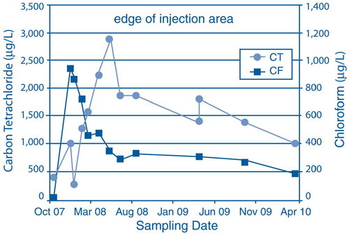
Different CT changes were observed at the edge of the injection area after the initial spike in CT transformation (Figure 2). In the five-month post-injection monitoring event, CT concentrations had increased while CF concentrations continued to decrease, which indicated that material delivery may have been insufficient to quickly reach all edges of the plume. Monitoring results from September 2008 to April 2010 indicate that the plume has slowly reacted, likely due to ongoing biological reductive dechlorination.
To evaluate long-term effectiveness of the ISCR treatment, groundwater sampling will continue on a semi-annual or annual basis. Pending Argonne's completed evaluation, the USDA/CCC will determine if this technology will be applied in full-scale remediation at the Centralia site or other USDA/CCC sites.
Contributed by Eugene Yan, PhD (eyan@anl.gov or 630-252-6322) and Lorraine LaFreniere, PhD (lafreniere@anl.gov or 630-252-7969), Argonne National Laboratory, and Caroline Roe, USDA/CCC ((caroline.roe@wdc.usda.gov or 202-720-9964)
Combined Cryogenic Compression and Condensation Process Used for Hydrocarbon Recovery
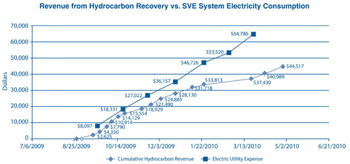
EPA Region 6 is implementing an innovative technology to collect and condense vapor from soil vapor extraction (SVE) and air stripping systems used to treat contaminated groundwater at the State Road 114 Superfund site in Levelland, TX. The technology uses cryogenic compression and condensation equipment to recover contaminant vapor as a liquid for potential recycling or resale. Since startup of groundwater treatment in August 2009, project revenue gained by resale of recovered hydrocarbon has offset nearly 70% of the SVE system’s electricity costs.
The State Road 114 site encompasses a former 64-acre refinery where liquid wastes were disposed in unlined pits and commingled processing materials were spilled between 1939 and 1954. The Texas Department of Health detected 1,2-dichloroethane (1,2-DCA) in 1990 while collecting samples from a well now operated by an onsite farmers co-operative. Investigations identified a 1.2-mile groundwater plume and approximately 717,000 ft2 of light non-aqueous phase liquid (LNAPL) with a median thickness of 0.5 feet. Contamination extends to 28 Ogallala Aquifer wells used for residential, public water supply, and commercial purposes.
Cleanup goals were set at the maximum contaminant level (MCL) of 5 µg/L for both DCA and benzene in drinking water, 170 µg/L for vanadium, and 10 µg/L for arsenic. Initial cleanup work involved extending municipal water supply lines to affected residences and businesses and excavating 3,600 yd3 of contaminated soil followed by onsite waste burial.
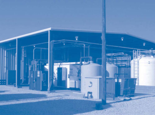
Designs for the groundwater treatment system included the cryogenic compression and condensation equipment as a means to collect and condense offgas from both the SVE well network and air stripping system. The cryogenic process relies on regenerative adsorption to recover VOCs as hydrocarbon material (re-condensation of vapors) that is immediately stored in two 6,500-gallon fiberglass-reinforced polyethylene tanks (Figure 3) and subsequently polished by filtration through granular activated carbon (GAC). A fuel tanker transports the recovered hydrocarbon to a fuel facility where it is mixed with oil blend stock to produce a low-grade fuel (similar to gasoline) ultimately traded as a commodity on the open market.
The groundwater extraction and restoration system includes 21 onsite and offsite extraction wells, 4 wells for injection of treated water, and 62 SVE wells for preventing or minimizing further migration of contaminants from the contaminant source, including LNAPLs. Upon extraction, groundwater is pumped through arsenic and manganese treatment units with chemical metering systems for metal flocculation. The process stream is then directed through two filter media vessels to two air stripping units, where chemical feed pumps equipped with an injection quill and static mixer add an anti-scaling agent to the stream. A defoaming agent also is added to reduce foam within the air strippers.
The air stripping system consists of two 6-tray,400-gpm units operating in parallel at a total rate of 400 gpm. Each unit consists of a skid-mounted stripping tower, a 30-hp fan blower for aeration, and a 7.5-hp centrifugal discharge pump. Before discharge to the atmosphere, air stripping off-gas is treated by a zeolite wheel concentrator rotor. The zeolite wheel concentrator uses a corrugated mineral fiber substrate that is permanently bonded with a mix of hydrophobic zeolite and other inorganic compounds capable of adsorbing VOCs from the effluent air stream. The concentrator turns several revolutions per hour, transporting VOC-laden zeolite into the regeneration zone and returning regenerated zeolite to the surface for continued VOC adsorbtion. The selected zeolite wheel concentrator can handle a capacity of 2,600-7,000 scfm of VOC-laden air.
Sequential steps in the cryogenic collection/condensation process involve: (1) drawing the soil gas and delivering it to the air compressor through use of positive displacement blowers; (2) separating entrained liquids at a water knockout tank from which the liquids are diverted to the groundwater treatment system; (3) compressing process air to approximately 150 psi; (4) removing water vapor from the process stream at air-to-air heat exchangers that cool the vapor stream to approximately 40°F; (5) additionally cooling the vapor stream to approximately -40°F in refrigerated heat exchangers, where the majority of chemical constituents are condensed and separated from the vapor stream; (6) sending the vapor stream to the regenerative adsorber, which removes any residual chemical constituents and water vapor and directs it back to the inlet stream; and (7) polishing the system effluent vapor stream through GAC filtration prior to discharge.
More than 99% of the VOCs are typically recovered from the vapor stream. Over time, the SVE system is expected to recover 285,000-570,000 gallons of hydrocarbon material. Integration of the cryogenic process is anticipated to result in an unlimited production rate (based on maximum yields from the compressors) and result in a five-year reduction in time needed to reduce the source zone at State Road 114. EPA Region 6 estimates an annual electricity cost of $129,600 for O&M of the cryogenic process, based on an annual demand of 185,000 kWh each year. (Figure 4).
Contributed by Vincent Malott, EPA Region 6 (malott.vincent@epa.gov or 214-665-8313)
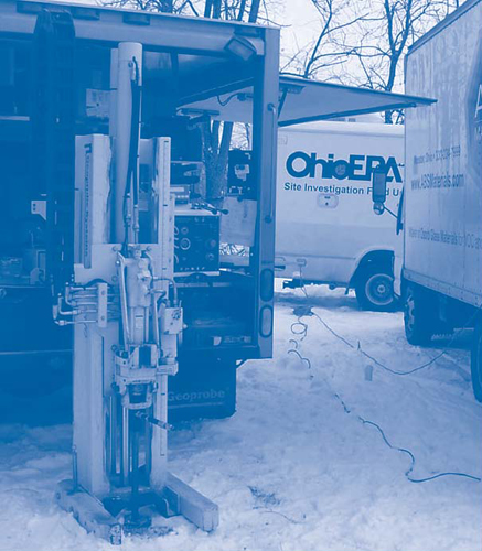
Ohio EPA Tests TCE Reduction Capacity of Nanoscale Metal-Silica Hybrid Materials
The Ohio Environmental Protection Agency (Ohio EPA) began a two-phase field test in July 2009 to assess the efficacy of injecting a metal-silica complex into the subsurface to remediate contaminated groundwater at the former Penn-Michigan Manufacturing Co. site in West Lafayette, OH. The tested complex contained nanoscale iron embedded in silica-based materials forming a fine-grained, glass-like powder that effectively acts as a contaminant sponge. Performance monitoring one month after the initial injection indicated an average 64% reduction in VOC concentrations in test-area groundwater.
In 1991, the Village of West Lafayette detected vinyl chloride in one municipal drinking water well. Subsequent Ohio EPA investigations discovered a 2,600- by 1,600-ft groundwater plume of trichloroethene (TCE) and its breakdown products, cis-1,2-dichloroethene and vinyl chloride. In the vicinity of past industrial operations, the TCE concentration reached a high of 1,500 µg/L. The plume is located approximately 60-120 feet below ground surface (bgs) in a sand and gravel aquifer with a groundwater flow rate of 0.5 ft/day.
Earlier laboratory testing at the College of Wooster, OH, indicated that the silica-based material would absorb and expand like a sponge when coming into contact with hydrophobic materials, including TCE and its degradation products, while excluding water, salts, and non-toxic metals. By adding nanoscale iron to the silica material, absorbed TCE molecules within the swollen matrix are degraded through reductive dechlorination to ethane gas and chloride ions that are expelled from the silica matrix as benign materials. The swelling and dechlorination process continues as the natural flow of groundwater brings additional TCE into contact with the reactive matrix.
Laboratory tests also indicated 1 kg of the silica complex embedded with nanoscale iron could reduce 30-56 kg of TCE prior to exhaustion of the reactive nanomaterials, depending on concentration loads and flow rates. Longitudinal studies determined the silica matrix to be a stable material that created no hazardous products, and soil tests showed no evidence of its interference with soil composition or plant growth.
The first injection at Penn-Michigan was performed on July 21, 2009, through use of a direct push rig. Due to its high hydrophobicity, the iron-silica matrix was injected in a sodium lauryl sulfate slurry to facilitate uniform distribution across a target radius of 15 feet. A total of 12 kg of the fine (200-350 mesh) powder was injected in one borehole at depths of 59, 64, and 69 feet bgs upgradient of an area of groundwater contamination with TCE concentrations ranging from 300 to 1,000 µg/L.
A fluorescent tracer was embedded in some of the silica-based material and injected concurrently with the iron-silica material in order to monitor the travel distance of the slurry across the test area. Post injection soil sampling indicated the slurry had traveled farther than the desired 15-foot radius, as evidenced by tracer material in soil 24 feet downgradient of the injection location. Eight soil borings within the test area indicated the matrix slurry had dispersed to an area larger than anticipated, spreading to a total volume of 52,000 ft3 instead of the targeted 14,000 ft3.
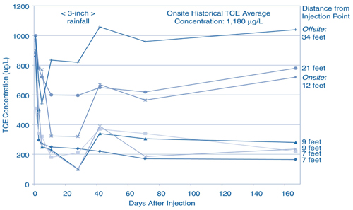
Groundwater was sampled over two months at six monitoring wells surrounding the injection point at distances of 7-15 feet. Results one month after the injection showed TCE concentrations 10-90% lower than pre-injection concentrations. Seven months later, groundwater sampling at four of the six wells showed TCE concentrations had rebounded slightly, with TCE concentration reductions varying from 0 to 61%. The absence of TCE degradation products in groundwater suggested that TCE was fully degraded by the iron-silica matrix. Offsite groundwater sampling 21 feet downgradient of the injection site showed a TCE concentration of 597 µg/L, a 40% reduction from the initial 1,000 µg/L.
The data suggest that the temporary TCE rebound was caused by 3 inches of rainfall that occurred between August 20th and September 3rd. The presence of iron that had not completely reacted with contaminants within the silica complex allowed the TCE reduction process to continue.
A second injection was administered in January 2010 to test an alternate formulation of nanometals, at a separate onsite location with TCE concentrations of 250-620 µg/L (Figure 5). The injectant consisted of 27 kg of nanoscale material consisting of 10% iron (%w/w) and 0.3-1% palladium (%w/w) embedded in the silica matrix. Test-area groundwater sampling in April yielded TCE concentrations of 200-500 µg/L, a 20-50% reduction from pre-injection levels. Overall results indicated the palladium formula performed comparably to the earlier iron-based media.
Results from both phases of Ohio EPA's field test suggested that delivery of material to the target zone was a limiting factor in implementation of this innovative technology (Figure 6). Due to its hydrophobic nature, the material did not easily distribute throughout the aquifer.
The cost of iron-silica material for the first injection was approximately $18,000, and slightly higher material costs were incurred for the palladium formula used in the second injection. Ohio EPA and vendor demonstration funds for monitoring, direct-push, and laboratory work were supplemented by an advanced engineering award the vendor received from the National Science Foundation
Sustainable Remediation Conference
The University of Massachusetts Amherst and U.S. EPA will hold the International Conference on Sustainable Remediation 2011: State of the Practice on June 1-3, 2011, in Amherst, MA. Presentation abstracts may be submitted by November 1, 2010, at: www.umass.edu/tei/conferences/
SustainableRemediation/.
A third trial was initiated by the vendor in late July 2010, using a newly developed injection probe. The probe is approximately 6 feet in length (in contrast to the 14-inch probe previously used) and contains additional injection holes to facilitate more even distribution of the silica-based material. The trial also involved injection of a higher volume (57 kg) of material to blanket the treatment area more thoroughly. If results of the latest trial are successful, Ohio EPA will evaluate this technology in late 2010 to determine its full-scale potential at the Penn-Michigan site.
Contributed by Chris Osborne, Ohio EPA (chris.osborne@epa.state.oh.us or 740-380-5258), Paul Edmiston, PhD, College of Wooster (pedmiston@wooster.edu or 330-263-2113), and Deanna Pickett, ABS Materials (d.pickett@absmaterials.com or 614-257-8943)
