![]() A newsletter about soil, sediment, and groundwater characterization and remediation technologies
A newsletter about soil, sediment, and groundwater characterization and remediation technologies
- EPA Studies Identify Techniques for Critical Leak Testing Prior to Soil-Vapor Sampling
- Vapor Intrusion Mitigated Through Solar-Powered Exhaust Systems
- Proposed Plan Offers Tiering Systems to Determine Preferred Alternatives for Vapor Intrusion
- Program Developed to Ensure Long-Term O&M and Performance of Vapor Intrusion Mitigation
- New Approaches Studied to Investigate Vapor Intrusion
This issue of Technology News and Trends highlights approaches to assessing, mitigating, and monitoring vapor intrusion (VI). Varied action levels for VI represent varying site-specific factors included in development of the action level
EPA Studies Identify Techniques for Critical Leak Testing Prior to Soil-Vapor Sampling
Online Resources
The vapor intrusion "Issues" area of CLU-IN provides an information compendium including EPA's 2008 Engineering Issue: Indoor Air Vapor Intrusion Mitigation Approaches, the Interstate Technology and Regulatory Council's 2007 Vapor Intrusion Pathway: A Practical Guideline, and the 2008 Detailed Field Investigation of Vapor Intrusion Processes report developed under the U.S. Department of Defense Environmental Security Technology Certification Program. Access these documents at: www.cluin.org/.
Researchers at EPA’s National Risk Management Research Laboratory (NRMRL) in Ada, OK, are developing quality assurance (QA) measures for soil-gas and sub-slab sampling methods that help differentiate contaminant vapors due to vapor intrusion from background sources. Recent research focused on measures to identify leakage of ambient air into conventional vapor probes, which can significantly impact sampling result.
During sub-slab or soil-gas sampling, ambient air may enter the sampling vessel (e.g., sampling bag or canister) through loose fittings connected to the probe or through openings or cracks in the concrete and bentonite seals used to isolate screened intervals. If leakage occurs and gas concentrations at the point of leakage are less than soil-gas concentrations, concentrations measured in a sampling vessel will be less than true concentrations in the subsurface. In the absence of leak testing, leakage is assumed to have occurred if anomalous results are observed; otherwise, measurements are assumed to be valid.
The QA measures for soil-gas leak detection involve use of a small, sealed chamber that can be integrated into an above-ground sampling train. Placement of the chamber directly on top of a sub-slab or soil-gas probe enables each component of the sampling train to be vacuum or pressure tested with a gas tracer such as helium (He). Valves or gas-tight, quick-connect fittings are used to isolate each component during testing and containerize the vapor.
To test integrity of fittings for the leak detection chamber, NRMRL used a peristaltic pump to create a vacuum of 97.3 kPa in the flowmeter and tubing of a laboratory-deployed sampling train. The vacuum was initially recorded every second and then relaxed to every 120 seconds as it gradually dissipated over 35 hours. The Ideal Gas Law was used to calculate flow rate into individual components of the sampling train. Results indicated nearly a complete vacuum, with leakage of only 0.72 standard cubic centimeters per minute. NRMRL considers leakage less than 1% of the flow rate to be insignificant and below the detection limit.
Similar QA measures can be used in the field to leak test boreholes. One method is to flood the detection chamber surrounding the top of a borehole with a gas mixture containing a tracer (usually He). Concentrations in the chamber and line or in the sampling vessel are then monitored. Typically, He is injected into the chamber as a pure gas, and a portable thermal conductivity detector (TCD) is used to monitor the sampling train. The density of dry, pure-phase He is only 0.16 g/L at 20°C, while the density of soil gas typically exceeds 1.2 g/L. As a result, pure-phase He is buoyant and will not be drawn down a compromised borehole without sufficient vacuum in a screened interval.
NRMRL developed a heuristic model (Figure 1) to provide a conceptual understanding of borehole leakage. Only vertical compressible gas flow is allowed down a compromised borehole having an integrated gas permeability of k1. The integrated permeability of the borehole incorporates the presence of cracks and openings in and around an essentially impermeable matrix of concrete and bentonite. Only radial compressible flow is allowed to a screened interval in a homogeneous isotropic medium having a gas permeability of k2.
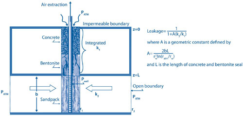
These calculations indicate that leakage is primarily a function of the permeability contrast between the formation and borehole. As the ratio of formation to borehole permeability decreases, the potential for leakage increases. The potential for leakage then is greatest in soil having low gas permeability.
The leak detection chamber was integrated into a borehole sampling train used to evaluate past releases from underground storage tanks at an automotive station in Green River, UT. Onsite soil consists primarily of clay, and the soil gas consists of 79.8% N2 and 20.2% O2, with a calculated density of 1.19 g/L at 20°C and 100% relative humidity. To minimize the effect of buoyancy, a gas mixture of He and argon (Ar) was injected to achieve a near-constant gas mixture inside a chamber of 42% Ar, 21% He, 7.8% oxygen (O2), and 29.2% nitrogen (N2) with a calculated gas density of 1.15 g/L at ambient temperature. A portable TCD and landfill gas meter were used to measure He and O2, carbon dioxide and methane in the sampling train and specifically within the chamber, respectively. QA tests indicated nearly 100% leakage in the borehole, which in turn prompted evaluation of whether to redesign or abandon the borehole.
NRMRL recommends that leak testing always precede soil-gas sampling, especially in media of lower permeability, until the integrity of a borehole is well established. All components of the sampling train should be vacuum or pressure tested with quantified flow into or out of the system prior to sample collection. For leak testing of conventional probes, a chamber containing a gas mixture approaching the density of soil gas should be used, and tracer concentrations in the chamber should be held constant in order to quantify the leakage.
NRMRL has developed purge and transient gas permeability test measures that can be used simultaneously with the leak detection methods. The concurrent testing process relies on multiple tracers introduced into multiple intervals of soil-gas probe clusters.
Contributed by Dominic Digiulio, NRMRL (digiulio.dominic@epa.gov or 580-436-8605)
Vapor Intrusion Mitigated Through Solar-Powered Exhaust Systems
EPA Region 6 undertook a Superfund removal action earlier this year at the Delfasco Forge site in Grand Prairie, TX, to address trichloroethene (TCE) vapor migrating from a groundwater plume. Region 6 and the State had determined after extensive site investigations that technologies such as soil vapor extraction or natural attenuation would require several years to remove or reduce the plume significantly. As a result, the time-critical removal now underway involves installing exhaust systems in offsite buildings with TCE vapor concentrations above the action level. Long-term, inexpensive operation of the systems is enhanced through use of solar energy to generate the electricity needed by the exhaust fans.
From 1981 until 1997, the Delaware Forge and Steel Company used less than two acres of the site for metal forging and fabrication that applied degreasing agents containing TCE. Studies in 2003-2005 indicated that degreaser spills and releases had led to contamination of shallow groundwater extending below an adjacent 65-acre area with approximately 500 homes and six light industrial businesses.
Investigations conducted in 2008 for RCRA corrective action involved collection of soil samples, air samples from crawl spaces and indoors, and sub-slab soil vapor samples to assess potential migration of contaminant vapor from the groundwater plume, which is located 18-32 feet below ground surface. Region 6 used EPA's TAGA van, a vehicle equipped with a trace atmospheric gas analyzer and summa-type canisters, to collect and analyze the air. TCE was detected in 18 homes with two showing concentrations above the action level of 14 µg/m3.
Passive air sampling also was conducted in the immediate four-block area to further define the vapor plume. Semi-quantitative samples were collected at 100 points over two weeks, at a unit cost of $18. Results further defined a soil vapor plume that is in the heart of the known groundwater plume and lies under approximately 12 homes.
This past January, Region 6 collaborated with the Texas State Health Services and the Agency for Toxic Substances and Disease Registry to conduct indoor air sampling in forty homes located in four areas of Grand Prairie. The sampling event was scheduled for mid winter, the time of year most likely to present a worst-case scenario of reduced ventilation and low TCE decomposition due to closed-up buildings. Results showed two additional homes with air contamination above the TCE action level, both of which are located in the area of the vapor plume earlier defined through passive soil-gas sampling. The State also collected blood samples from residents of all 40 buildings.
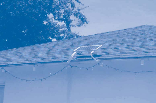
Most of the homes in this neighborhood are "pier and beam" structures with underlying crawl spaces. This architectural design prompted use of an exhaust system that could evacuate air in the crawl space and prevent TCE buildup and additional migration into the home's interior. The simple mitigation design allows a commercially available fan to be powered by a solar energy unit (Figure 2), which saves the homeowner an estimated $96/year for electricity.
To date, exhaust systems have been installed in the four homes found to have TCE concentrations exceeding action levels. Each system consists of a conventional 6-inch, 200-CFM fan installed in the crawl space and is powered by a 10- by 16-inch, 10-watt solar panel mounted on the building’s roof. Each solar panel can be supplemented by a 24-volt battery with a lifespan of 5-7 years to ensure continuous operation of the exhaust system. System installation was completed in two days, including less than one hour for solar panel installation. Equipment costs for each system included $200 for the fan and the solar panel, and $50 for the battery.
Homes with slab foundations will require a subsurface mitigation system involving lateral pipes between sumps typical of radon fan systems. Project plans estimate that each subsurface exhaust system will employ a 65-watt radon fan operating at a rate of 200 CFM and powered by a 36- by 36-inch solar panel. A subsurface system can be installed within 10 days. Equipment costs are anticipated to include $1,500 for each radon fan and $800 for each panel.
Post-installation sampling of two exhaust systems indicated an immediate 95% reduction in TCE vapor in each building’s interior. Exhaust systems will be offered this fall to 10 additional homes in the area defined by soil-gas sampling. If additional homes are found above the action level, exhaust fan systems will be offered to the homeowners.
Contaminant migration from the Delfasco Forge groundwater plume is expected to continue for up to 30 years. As a result, Region 6 is gathering information to evaluate the site’s potential inclusion on the National Priorities List (NPL).
Contributed by Greg Fife, EPA Region 6 (fife.greg@epa.gov or 214-665-6773)
Proposed Plan Offers Tiering Systems to Determine Preferred Alternatives for Vapor Intrusion
EPA Region 9 has issued for public comment a proposed plan to mitigate VI in commercial and residential buildings at the Middlefield Ellis Whisman (MEW) Study Area, which includes three NPL sites in Mountain View and Moffett Field, CA. Formerly used for industrial and semiconductor activities, this area has undergone extensive soil and groundwater remediation to remove TCE and other contaminants in compliance with a 1989 record of decision (ROD).
As part of a supplemental remedial investigation from 2003-2008, over 2,800 air samples, including indoor, outdoor, and pathway air samples, were collected at 47 commercial and 31 residential buildings. TCE was found to exceed EPA Region 9's TCE interim action levels in several buildings. As a result, discrete mitigation methods were implemented (e.g., sealing conduits, enhancing ventilation, and installing sub-slab ventilation systems) to reduce indoor air concentrations.
The proposed plan presents EPA's preferred alternatives for protection of building occupants from potential long-term exposure to VI. Two tiering systems, one for existing and one for future buildings, are proposed. Detailed decision trees were developed to help assign each building a proposed action based on sampling results. Depending under which tier it falls, a building may require an engineered remedy, monitoring, and/or institutional controls.
Following consideration of all public comments extended through October 8, 2009, EPA will select the VI remedy in a ROD amendment and then work with the responsible parties to implement the remedy. For more information, see www.epa.gov/region09/MEW.
Contributed by Alana Lee, EPA Region 9 (lee.alana@epa.gov or 415-972-3141)
Program Developed to Ensure Long-Term O&M and Performance of Vapor Intrusion Mitigation
EPA Region 7 has developed a comprehensive VI program to address the installation and long-term operation and maintenance (O&M) of VI mitigation systems, as well as assessment sampling for future systems, in homes near the Chemical Commodities, Inc. Superfund site (CCI). Region 7's VI Program Implementation Manual, which describes decision processes and procedures as well as roles and responsibilities for these activities, is helping ensure protection of area homes and information outreach to the community.
The CCI site is an inactive chemical recycling facility located in central Olathe, a suburb of Kansas City. From 1951 until 1989, the facility stored and processed a variety of chemicals including surplus industrial and laboratory chemicals, many of which were hazardous substances and wastes. Materials were stored in aboveground and underground storage tanks and other containers throughout the site. Poor handling and housekeeping practices led to spills, leaks, and fires.
Following a fire in 1977, site investigations found that soil and groundwater at CCI were contaminated with elevated levels of metals, pesticides, PCBs, semi-volatile organic compounds, and volatile organic compounds (VOCs). Subsequent investigations indicate that the groundwater contaminant plume extends offsite, having migrated at least a distance of 1,000 feet beneath a neighborhood west of the site. Cleanup activities have included removal of stored chemicals from the site, limited excavation of onsite soil, and removal of all onsite buildings.
In 2001, the EPA began investigating the possibility of vapor intrusion into nearby homes. Air sampling performed in homes around the CCI facility found that VI raised concern for potential exposure to some residents. TCE was found to be the most prevalent VOC in the groundwater and was detected above the health-based action level in several homes.
As a result of these findings, EPA signed an action memorandum calling for installation of VI mitigation systems in homes near CCI. The Boeing Company, one of several potentially responsible parties, agreed to pay for and install VI systems in those homes identified by the EPA and to further assess additional homes in other nearby neighborhoods. Homes were selected for sampling based on their proximity to the CCI site and on the data collected during site characterization. Those with indoor air levels of target substances above the action levels (e.g., greater than 2 µg/m3 for TCE) qualified for a VI system. However, residents had the option of turning down installation of a system.
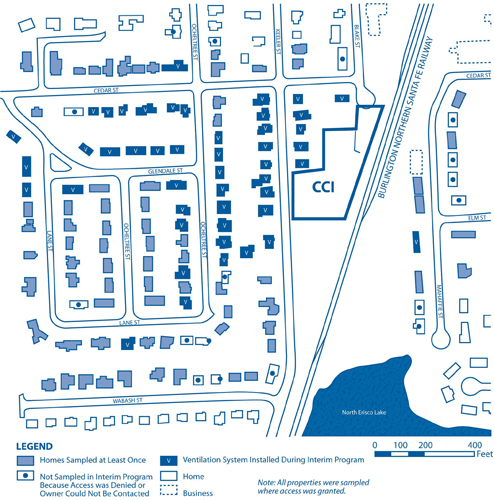
In total, indoor air was sampled in more than 100 homes and VI systems were installed in 45 homes (Figure 3). The VI systems are the same as those used to remove naturally occurring radon in parts of Kansas. A collection pipe was placed on the ground beneath homes with crawl spaces and vapor barriers were installed. Vapors collecting in the pipe from beneath the vapor barrier are extracted with a fan and vented to the outside via a vertical exhaust pipe that discharges above the roof. Homes with basements are vented to the roof by placing the vertical pipe through the concrete slab and into the subsurface.
The final remedy specified in a 2005 ROD includes a long-term VI program as part of the overall approach to groundwater remediation at the site. Region 7 is responsible for the O&M of the VI systems and O&M work, which will be overseen by Region 7, involves annual routine inspections to verify that each system is working properly. Before the first inspection, the homeowner must sign an access agreement that will allow EPA and its contractors to enter the home to perform O&M. The inspections take note of any structural changes to the home that may have occurred since the installation of the VI system or previous inspection which could impact the effectiveness of the system.
In addition to O&M, the VI program includes assessment sampling for homes without VI systems, installation of additional VI systems as necessary, and performance monitoring of any newly installed systems. The need for additional assessment sampling will be largely based on groundwater data, which could indicate plume migration into areas that have not previously been tested.
Overall, the VI systems installed in Olathe have been effective at reducing contaminant levels to levels below the EPA action levels. Annual inspections have revealed that most frequent problems involve tears or rips in the membranes and inadequate sealing around the edges of the vertical pipes. Many of the membranes have been replaced with a heavier-duty material, and pipes have been properly sealed. The mechanical components generally have had few problems. Because the VI systems have a life expectancy of 10-15 years, EPA anticipates the need to periodically replace mechanical components such as fans as the systems age over time.
Contributed by Mary Peterson, EPA Region 7 (peterson.mary@epa.gov or 913-551-7882)
New Approaches Studied to Investigate Vapor Intrusion
In 2008, EPA Region 9 received an EPA RARE grant (Regional Applied Research Effort) to evaluate three promising techniques for VI assessment of indoor air: (1) using radon as a surrogate for assessing VOC VI; (2) using modified sorbent-based methods for longer, time-integrated measurements of indoor air VOCs; and (3) using building pressure differentials to assess the potential for VI. Available indoor air analytical methods are relatively expensive, so additional research is needed to develop cost-effective methods to evaluate vapor intrusion into individual buildings.
Region 9's cross-program team in collaboration with EPA's Office of Research and Development is comparing the results of the three techniques with the goal of improving and demonstrating cost-effective and health-protective alternative approaches for assessing vapor intrusion and indoor air quality in homes and commercial buildings. The EPA team conducted concurrent field testing of these methods at Orion Park Housing, a vacated military residential area at the Naval Air Station Moffett Field Superfund site in California. Preliminary data indicate promising results for longer-duration, modified sorbent-based methods for selected VOCs. The next phase of the field work will focus on testing the pressure differentials and active and passive sorbent-based methods in commercial buildings at NASA Ames Research Center in California. Study results are expected in 2010.
Contributed by Kathy Baylor, Region 9 (baylor.katherine@epa.gov or 415-972-3351)
