
- Featured Articles
- Assessment and Mitigation: Defining and Addressing Vapor Pathways in a Mixed Use Area
- Mitigation and Monitoring: The Need to Tailor Sub-Slab Depressurization Systems
- Resources
- CLU-IN
- EPA Office of Solid Waste and Emergency Response (OSWER
- National Priorities List (NPL)
- Underground Storage Tanks
- Recent Publications
- Draft Final Guidance
 Download This Issue in Adobe PDF® Format
(1.43MB/9pp/PDF)
This issue of Technology News & Trends highlights vapor intrusion (VI), which generally refers to migration of hazardous vapors from any subsurface contaminant source such as contaminated soil or groundwater through the vadose zone and into indoor air. Vapor intrusion can occur in a broad range of land use settings, including residential, commercial, and industrial properties, and can affect buildings with virtually any type of foundation such as basement, crawl space, or slab on grade. Assessing human health risks posed by VI and determining the optimal method for mitigation, where needed, is typically complicated by variance in natural attenuation of migrating vapors and the mixing of those vapors with other sources of indoor air contaminants. Assessment also can be difficult due to heterogeneous subsurface conditions and preferential pathways for vapor migration and soil gas entry.
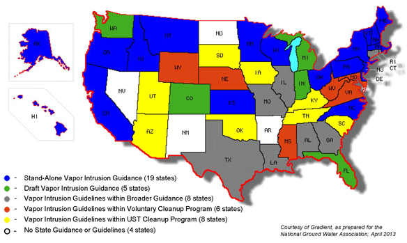
The VI pathway has become a standard consideration during investigations at hazardous waste sites, especially those subject to the Superfund, underground storage tank (UST), and Resource Conservation and Recovery Act programs operated by federal or state agencies. The U.S. Environmental Protection Agency (EPA) currently is finalizing its guidance on subsurface VI. In addition, 24 states issued draft or final VI guidance as of April 2013, and other state guidance continues to evolve. Earlier this year, for example, the New Jersey Department of Environmental Protection updated its Vapor Intrusion Technical Guidance for use in evaluating VI pathways at contaminated sites within New Jersey. Later this year, VI-related guidance or rulemakings are anticipated in Illinois and Pennsylvania. In some states, VI guidelines have been incorporated into broader guidance or into programs covering voluntary cleanup or underground storage tanks.


Assessment and Mitigation: Defining and Addressing Vapor Pathways in a Mixed Use Area
Contributed by Vickie Meredith (WYDEQ), Jeff Kurtz (EnviroGroup, Ltd.), and Coleman Hoyt (EnviroGroup, Ltd.)
In 2010 and 2011, the Wyoming Department of Environmental Quality (WYDEQ) installed mitigation systems in 24 residences and one commercial building to prevent intrusion of trichloroethene (TCE) and tetrachloroethene (PCE) vapors from an orphan site in downtown Cheyenne. The source had been previously identified as a 20-acre groundwater PCE plume. A three-phase investigation conducted between 2009 and 2011 included the collection of groundwater, soil gas, indoor air, and sub-slab vapor samples to evaluate the potential for vapor intrusion (VI) in area buildings. Residential buildings in areas of high soil vapor PCE concentrations (above 810 micrograms per cubic meter [µg/m3]) were offered pre-emptive mitigation systems, while buildings in the surrounding areas were investigated further before potentially being selected for mitigation.
PCE and TCE were discovered in area groundwater in 2002 following a Phase II environmental site assessment conducted as part of a proposed expansion for a local grocery store. A more thorough site investigation was conducted in 2003 and 2004 to evaluate the nature and extent of this groundwater contamination and the potential for VI. The investigation identified a 20-acre groundwater PCE plume located 10-20 feet below ground surface (bgs) and low levels of TCE. PCE levels ranged as high as 450 micrograms per liter (µg/L) in groundwater samples and as high as 54,259 µg/m3 in soil gas samples. Based on these investigations, potential contaminant sources were determined to include two former auto repair shops, a former printing shop, as well as existing and former dry cleaners.
A follow-up study was conducted in 2009 to further evaluate the nature and extent of volatile organic compounds (VOCs) in soil vapor and groundwater, the potential for VI, and whether VI controls were warranted for site buildings. Eighty-three shallow soil vapor probes (to a depth of 5 feet bgs) and 31 sub-slab vapor probes were installed and sampled throughout the area (Figure 1). Groundwater samples were collected from 18 permanent wells (mainly screened from 7 to 17 feet bgs across the water table), three temporary groundwater monitoring points (installed to depths of 10 to 17 feet bgs), two existing monitoring wells, two private wells, and four sumps in the study area. PCE and TCE concentrations in soil vapor samples were analyzed in a mobile laboratory, which provided real-time information on the nature and extent of VOCs and allowed rapid evaluation of suspected source areas, transport pathways, and potentially impacted buildings. To demonstrate comparability of mobile laboratory sample results, samples also were collected from 16 of the 83 soil vapor probes for fixed-based VOC laboratory analysis. Soil vapor data were used to evaluate plume extent and better define and characterize source areas. Twenty outdoor air samples were collected concurrently in the vicinity of indoor air and sub-slab vapor samples to provide information on ambient levels of PCE and TCE.
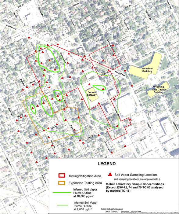
Figure 1. Inferred PCE concentrations and soil vapor sampling locations.
Eighteen soil vapor samples collected during the 2009 sampling event indicated the presence of PCE above the WYDEQ soil vapor screening level of 810 µg/m3, which was selected by WYDEQ based on a 1x10⁻⁵ target indoor air concentration cancer risk level of 8.1 µg/m3. Buildings in the area above this screening level were considered to have the highest potential for VI risk. All 32 owners of residential buildings in the high PCE zone were offered pre-emptive mitigation and indoor air testing, of which eight accepted and 18 chose indoor air testing prior to installation of mitigation systems. A total of 14 pre-emptive mitigation systems were installed. The owners of the 31 commercial buildings in this zone were offered indoor air and sub-slab vapor testing to determine the need for further action. An additional 19 homes peripheral to the high PCE zone were offered indoor air testing. Only two of these peripheral homes were found to have indoor air PCE concentrations above the screening level.
From July to August 2010, a second phase of the investigation was implemented to further define the extent of PCE in soil vapor along the western edge of the high PCE zone. Eleven soil vapor samples indicated PCE concentrations above 810 µg/m3, leading to the expansion of indoor air and sub-slab testing areas in early 2011 to include an additional 34 residential buildings. The investigative zone was further expanded in July 2011 to the southern and western edges of the previously examined areas, but no additional areas of high soil vapor PCE were identified.
Over the course of the three investigative phases, indoor air samples were collected from a total of 52 homes, three apartment buildings, and 30 commercial buildings. PCE was detected (detection limit 0.22 µg/m3) in nearly all indoor air samples, with measured concentrations ranging as high as 62 µg/m3. PCE exceeded screening levels (residential=8.1 µg/m3; commercial=27.2 µg/m3) in 13 residential and 2 commercial buildings. TCE was detected (detection limit 0.17 µg/m3) at concentrations ranging up to 5.6 µg/m3. Six of the residential and none of the commercial buildings sampled exceeded TCE screening levels (residential=0.9 µg/m3; commercial=4.2 µg/m3). The possibility of indoor VOC sources was eliminated by completing a chemical inventory and questionnaire for each building prior to sampling. Residents also were asked to avoid bringing dry-cleaned clothes into their homes for 1-2 weeks prior to testing. In buildings where indoor VOC sources were suspected, WYDEQ collected additional samples or examined soil gas and groundwater ratios of TCE and PCE.
Mitigation systems were installed in 24 residences (including 14 pre-emptive mitigation systems) and one commercial building over the three-year investigative period. These buildings included single-level residential, multiple-level residential, and commercial structures with poured concrete, block, and brick foundations. Basements and/or crawlspaces were present in each building. The type of mitigation system selected was based on the number of buildings over the plume, their size and basic structure, and the presence of unsaturated and semi-permeable soils below the slab.
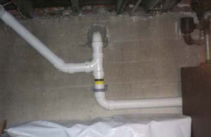
Figure 2. SMD and SSD vent lines, penetrating the concrete foundation wall.
A combination of mitigation technologies was selected based on site-specific conditions. Nine residences received sub-slab depressurization (SSD) systems, which use a fan to remove air from underneath the slab and exhaust it above the building, creating a negative pressure. A minimum negative pressure below the entire slab of -0.003 inches water column compared to indoor air pressure was considered sufficient. Eight residences and the commercial facility received a combination of SSD and sub-membrane depressurization (SMD) systems; SMD systems (used in accessible crawlspaces) involved installation of a membrane over a perforated pipe on the dirt floor and use of a fan to remove air from below the membrane and exhaust it above the building (Figure 2). Simple crawlspace ventilation, which increases the air exchange rate for a crawlspace, was utilized in two residences where only a crawlspace was present but inaccessible. A combination of two or all three systems was employed in the remaining five residences. Several low-vacuum/high-flow fans were used primarily on crawlspace foundations or slabs with coarse sub-slab fill, and a single higher vacuum/lower flow fan was used on basement or slab on grades with sand or lower permeability fill.
Performance testing was conducted in 17 of the 25 buildings with the heating, ventilation, and air conditioning (HVAC) units operating under normal conditions. The buildings requiring performance tests were those with either partial or complete crawl space ventilation mitigation systems or other types of systems with poor mitigation system diagnostics. Based on test results, two of the buildings required system enhancements. After system upgrades, both of these buildings, operating under normal HVAC conditions, had indoor air results well below screening levels. Contaminant concentrations were below screening levels in the remaining buildings undergoing performance testing.
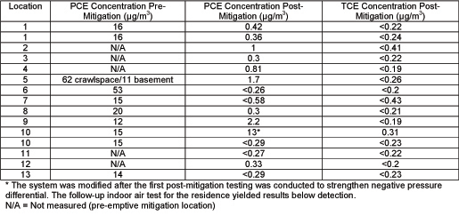
Table 1. Indoor air concentrations of PCE and TCE before mitigation and 2-7 months after mitigation began.
Subsequent indoor air samples collected from several of the mitigated buildings 2-7 months after the installation date indicated a reduction in PCE concentrations from 11-62 µg/m3 to less than 1 µg/m3 in most residences, and a reduction in TCE concentrations from 0.17-5.6 µg/m3 to non-detectable levels (Table 1). Mitigation systems are operated by individual homeowners, and no further sampling is currently planned. The total cost of the groundwater, soil vapor, and indoor air investigations, installation of all mitigation systems, and other VI activities conducted from September 2009 to March 2012 is estimated at $635,000.
Mitigation and Monitoring: The Need to Tailor Sub-Slab Depressurization Systems
Contributed by Jim DiLorenzo, U.E. Environmental Protection Agency, Region 1)
Cleanup at the Nyanza Chemical Waste site in Ashland, Massachusetts, began in 1987 to address sludge contaminated with numerous volatile and semi-volatile organic compounds that had settled in onsite wetlands. Due to the need for pumping and treating contaminated groundwater at this National Priorities List site for as many as 30 years, the U.S. Environmental Protection Agency (EPA) Region 1 office initiated indoor air testing in 1990 that culminated in a 2006 decision for active mitigation to address trichloroethene (TCE) vapors already migrating from the groundwater into 43 buildings. Plans for installing and long-term monitoring of each vapor intrusion (VI) mitigation system involved detailed assessment of each building and multiple discussions with the property owners.
The site encompasses a facility that produced textile dyes from 1917 to 1978. A large groundwater plume of predominately TCE was found extending from the facility beneath adjacent residential areas and discharging to the nearby Sudbury River. The TCE plume is primarily within the overburden sand aquifer but also extends into bedrock fractures about 80 feet below ground surface. The water table is shallow and varies from ground surface at the river to a maximum seasonal depth of about 15 feet below ground surface. Measured TCE concentrations reached 6,000 micrograms per liter (µg/L) within the overburden aquifer and 20,000 µg/L in bedrock.
The site investigation expanded to indoor air sampling in 1998. Based on EPA's 2002 draft guidance for evaluating VI to indoor air pathways, TCE vapor in numerous offsite buildings presented an unacceptable indoor inhalation risk. Overall, EPA identified unacceptable TCE concentrations in indoor air at seven of 14 single and multi-family residential homes within half a mile of the facility as well as the municipal Town Hall.
Using a pre-emptive approach that considered multiple lines of evidence, mitigation systems were installed in 43 homes and the Town Hall in 2007. EPA determined that active sub-slab (SSD) depressurization would most effectively prevent TCE vapors from entering the buildings. Other active methods such as drain tile depressurization, block wall depressurization, active soil pressurization, and positive building pressurization were deemed infeasible due to building types and lack of available performance data and in consideration of relative operational costs. Sub-membrane depressurization was considered in several homes with dirt-floor basements but dismissed due to concerns about long-term integrity of the membrane fabric. Instead, new concrete was poured where necessary.
The SSD systems were of a typical design that includes four-inch-diameter PVC piping installed through the basement floor and into the sub-slab extraction pit. The piping routes outside the home and attaches to a single, continuously operating low-pressure mitigation fan (typically 90 watts). Piping extends from the fan to above the roofline, where vapors discharge to the atmosphere.
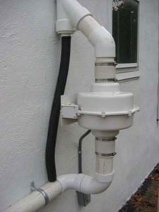
Figure 1. Configuration of exterior components in each installed VI mitigation system.
Other system components include a manometer for continuous pressure measurements, an exhaust pipe cap to prevent debris and rain from entering the exhaust system, a low-decibel alarm to warn of unintended system shutdown, and a minimum of two permanent monitoring points in the floor for pressure field extension tests (PFETs). A ¾-inch inner diameter condensation bypass tube also was installed adjacent to the fan to prevent excess moisture from entering the impeller (Figure 1). In some buildings, air-tight sump pumps were also installed. Some buildings required more than one extraction pit to achieve a negative pressure field. In these cases, piping from each extraction pit was fitted with a ball valve to manually regulate pressure flows between extraction pits.
As part of the planning process, EPA met with each property owner and tenant to gain consent for property access. EPA inspected each basement to evaluate factors such as household contents, physical access, available working space, foundation type and integrity, electrical controls, and any unique issues such as structural challenges, dirt floors, asbestos, and inadequate electrical service. Electrical permits were required at all properties, and construction permits were required for buildings where concrete slabs were installed. EPA then met again with each property owner and tenant to discuss the proposed system layout.
To ensure adequate flow and fan/pipe sizing in each building, PFETs were performed by drilling three 1-inch holes in the slab: one in the location of the planned extraction pit and one at each of two permanent monitoring points. Using a shop vacuum, suction was applied to the extraction pit hole. Resulting negative pressures were measured at the two monitoring holes using a digital micromanometer. Where concrete slabs were installed to replace dirt floors, PFETs were performed after the poured concrete fully cured. PFET results confirmed that a 90-watt fan would provide sufficient vacuum for all 43 homes; however, several buildings required a second or third extraction pit to generate a sufficient negative pressure field and the large Town Hall required a 140-watt fan. Based on the collective inspections and PFET results, one set of design specifications was developed and applied to a unique system configuration for each property.
Prior to installing each SSD system, below-grade foundation walls and slabs were sealed and basement contents were removed and temporarily stored in room-sized storage and shipping containers. Portions of drywall also were removed from some finished basements. The extraction pit was created by cutting a 12-inch concrete square from the slab and then removing sub-material to a depth of about 12 inches to maximize air flow. During interior pipe installation, care was taken to ensure the pipes maintained a slight slope to the extraction pit, in order to drain excess water from sub-slab moisture and exhaust stack condensation. Electrical work included installing two dedicated circuits for the fan and alarm.
Municipal permit inspections were performed by the local jurisdiction's building department. After a system had operated for about two weeks, its baseline vacuum pressure was measured by the manometer as 1 to 2 inches of water column and recorded. A final PFET was performed at that time using the permanent monitoring points to confirm an adequate negative pressure field was present under the slabs. A minimum vacuum pressure of 0.004 inches of water column (1 Pascal) was considered adequate and achieved in all systems. Since a negative pressure was being applied, a backdraft test was conducted in each building to ensure noxious gases from the HVAC system would continue venting outside the building.
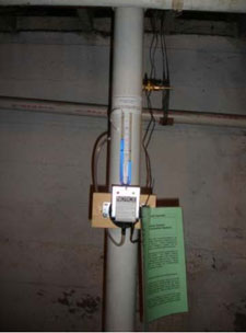
Figure 2. Instruction sheet with basic information about the system, explanation on how to respond to an alarm alert, and contact information.
A laminated instruction sheet attached near the system's alarm helps the property owner or tenant operate the system (Figure 2), and a dedicated hotline is available for owners with additional questions or experiencing an alarm alert. Maintenance and monitoring (M&M) of VI mitigation systems associated with this Superfund site is provided by the Massachusetts Department of Environmental Protection (MassDEP). The 10-year M&M plan developed jointly by EPA and MassDEP requires PFETs on about 25% of the systems each year, with the objective of verifying an adequate negative pressure field beneath the slabs. Visual basement inspections are performed each year on the remaining systems to verify conditions of the fan and piping and to confirm that the manometer pressure has remained constant.
EPA's Region 1 office spent $1.2 million to design and install the SDD systems. The average system cost of nearly $30,000 is higher than suggested in available guidance due in part to the general age and construction of the mitigated buildings. A majority of the buildings had fieldstone walls and dirt-floor basements. In the few buildings with poured concrete basements, the average cost was below $10,000. The cost of electricity needed to operate each system, estimated at $10-$20 per month, is the property owner's responsibility. MassDEP committed $600,000 to fund M&M of the systems over 10 years.
RESOURCES
CLU-IN: Vapor Intrusion
This issue area of the CLU-IN website provides an overview and compendium of guidance materials, site investigation tools, mitigation methods, and other information resources to help address volatile chemicals migrating from contaminated groundwater or soil.
EPA Office of Solid Waste and Emergency Response (OSWER): Vapor Intrusion
This website provides key information on VI for members of the public who may be interested in this topic, including community leaders and environmental professionals. This resource provides basic information about VI, technical and policy documents that may be used to support environmental investigations, and highlights of current and upcoming Agency activities related to VI.
National Priorities List (NPL): Vapor Intrusion and the Superfund Program
This EPA website provides key information on VI in context of the Superfund program. It provides electronic links to general information about VI and features details regarding potential addition of a subsurface intrusion (including VI) component to the Hazard Ranking System used to place uncontrolled waste sites on the NPL.
Underground Storage Tanks: Petroleum Vapor Intrusion (PVI) Compendium
The PVI Compendium maintained by EPA's Office of Underground Storage Tanks (OUST) provides electronic links to information on fate and transport, site characterization, soil gas sampling, remediation, and EPA or state guidance concerning migration of vapors from petroleum hydrocarbons such as gasoline, diesel, or jet fuel. Materials available for downloading include the "PVI Database," which contains relevant data from 74 sites.
Recent Publications:
- Fluctuation of Indoor Radon and VOC Concentrations Due to Seasonal Variations: This September 2012 report (EPA/600/R-12/673) presents a full year of weekly measurements of sub-slab soil gas, external soil gas, and indoor air on a single house that is impacted by VI of radon and volatile organic compounds (VOCs). In addition, the research evaluated the long-term performance of sorbent-based sampling devices for time-integrated measurement of indoor air levels of VOCs
- Evaluation Of Empirical Data To Support Soil Vapor Intrusion Screening Criteria For Petroleum Hydrocarbon Compounds: This January 2013 report (EPA 510-R-13-001) evaluates empirical data and selected modeling studies of petroleum hydrocarbon vapor behavior in subsurface soil at petroleum-UST release sites and describes how these vapors can affect subsurface-to-indoor air VI. The report presents an inclusion distance approach for screening petroleum release sites for VI. EPA's OUST developed the approach to improve the efficiency of investigating sites involving petroleum release and to focus resources on sites of most concern for petroleum VI.
Draft Final Guidance: Subsurface Vapor Intrusion Guidance
On April 16, EPA released for public input two draft final VI guidance documents: one general guidance applying to all compounds and one focused guidance applying to petroleum hydrocarbons released from USTs. When final, this guidance will help ensure that VI exposure assessment and mitigation actions to protect human health are undertaken in a technically, scientifically, and nationally consistent manner. Public comments must be submitted by June 24, 2013. Interested stakeholders can also register online for email updates about development and anticipated release of the final guidance from EPA's OSWER.
Contact Us:
Suggestions for articles in upcoming issues of Technology News and Trends may be submitted to
Linda Fiedler via email at fiedler.linda@epa.gov.
Past Issues:
Past issues of the newsletter are available at http://www.clu-in.org/products/newsltrs/tnandt/.
Archives | Subscribe | Change Your Address | Unsubscribe
