 A newsletter that provides descriptions and
performance data for innovative source control technologies that have been
applied in the field.
A newsletter that provides descriptions and
performance data for innovative source control technologies that have been
applied in the field.
|
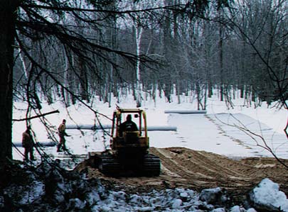
May 1999 “Snow Cap” Used for Sediment Remediationby Lisa Gutknecht, Wisconsin Department of Natural Resources, and Mick Warner, RMT, Inc. A new method was employed for constructing a cap over lead-contaminated sediments in a shallow, oxbow lake in Wisconsin. Using a geomembrane and sand, a “snow cap” was constructed during the winter, which then slowly settled over the lake in the spring as the snow melted. In addition to costing significantly less than conventional (and environmentally invasive) sediment dredging in terms of both funding and time resources, this technique offers the advantage of providing a safe habitat for existing fish populations. The snow cap was installed during February 1997 at a former battery reclaiming site near Wausau, WI. The capped area consists of a four-acre oxbow lake adjacent to the Rib River, which serves as an important breeding habitat for small fish. The lake is not part of the river channel, but includes flow-through areas. During spring thaw and heavy rain events, the lake is inundated by the adjacent river. Soft sediment impacted with lead has covered the lake bottom at an average thickness of two feet. This sediment consists of fine particles that could be re-suspended easily if disturbed. Prior to treatment, lead concentrations in the sediment ranged as high as 540 mg/kg at a depth of 0-0.5 feet, and 850 mg/kg at 0.5-1.3 feet. The four-layer composite cap used for this site includes a geotextile and sand blanket over the impacted area, and a second layer of geotextile and rock “islands.” The geotextile keeps sediment from migrating into the sand, and sand from migrating into the rock “islands” that serve as a spawning habitat. Snowmobiles were used to pack the snow and increase the ice thickness from 6 to 24 inches, thus providing support for heavy, wheeled construction equipment. By constructing the cap on top of the frozen lake, the creation of a “mud wall” (typically formed when water capping begins at a shoreline and pushes the cap materials outward over the sediment) was avoided. The formation of such mud walls commonly re-suspends contaminated sediment and prevents adequate contaminant containment. Installation of the cap on top of the frozen lake also allows the geotextile to be spread during a longer time frame, overlapped uniformly, inspected prior to covering, and placed without sediment disturbance (Figure 1).
Islands for providing habitat for small fish and other benthic organisms were installed at nine locations within the lake. These benthic islands consist of irregularly shaped rock on top of the sand. A second layer of geotextile material was placed between the rock and sand to prevent settling of the rock. The islands were constructed of a total of 300 tons of rock covering approximately 10 percent of the lake bottom. Rock layers were placed at the inlet of a small tributary to the river’s oxbow and at the small outlet of the oxbow to prevent erosion of the sand cap from flows in these areas. Analysis of field data collected at five sampling locations during March 1999 found current lead concentrations in the water column to be at background (3-6 mg/kg) or non-detect levels, indicating that no impacted sediment or sediment interstitial water is migrating through the geotextile or upper sand layer of the cap. In addition, populations of benthic organisms were noted in the shallow water areas in leaf litter, and submergent vegetation is becoming established on the new substrate. To ensure the cap is performing effectively, Wausau Steel will perform annual inspections of the cap’s physical integrity, and the Wisconsin Department of Natural Resources will conduct periodic testing of the pore water. In comparison to alternative dredging and removal of the contaminated sediment, it is estimated that this remediation approach cost approximately one-third of the cost to remove the sediment, for a savings of $1 million. New technologies such as the snow cap are needed in the Great Lake ecosystem to address the variety of toxicants found in the area. This project constituted the first full-scale, full-coverage sediment cap installed in Wisconsin. The feasibility of installing snow caps at other sites in the future will be evaluated on a site-by-site basis, taking into account the hydrological characteristics of the site. Contact Lisa Gutknecht (Wisconsin Department of Natural Resources) at 715-359-6514 or E-mail gutknl@dnr.state.wi.us, or Mick Warner (RMT, Inc.) at 608-831-4444 or E-mail mick.warner@rmtinc.com, for more information.
DOE Comparison of Landfill Cover Designsby Stephen Dwyer, Sandia National Laboratories The U.S. Department of Energy (DOE) Sandia National Laboratories is conducting a five-year, large-scale field demonstration comparing landfill cover designs at a test facility on Kirtland Air Force Base in Albuquerque, NM. This demonstration, known as the Alternative Landfill Cover Demonstration (ALCD), is evaluating two conventional and four alternative cover designs based on their respective water balance performance, ease of construction, and cost. Analysis of the first two years of data collected in this five-year demonstration are confirming earlier field experiences that conventional cover designs under RCRA Subtitle C and D are vulnerable to regional geologic and climatic conditions. To date, higher performance is exhibited by two of the less costly alternative designs. The ALCD test covers were installed side-by-side for direct comparison. Two baseline conventional covers were constructed, one in accordance with performance standards for RCRA Subtitle D soil covers and the second for Subtitle C compacted clay covers. Alternative designs include a geosynthetic clay liner, capillary barrier, anisotropic barrier, and evapotranspiration cover. Each test cover is 13 meters wide by 100 meters long, with a 50-meter, 5 percent slope in all layers. One side of the slope is monitored under ambient conditions, while a sprinkler system provides additional moisture on the other side to facilitate stress testing. The conventional soil cover is 60 cm thick, including a 45-cm bottom layer of compacted soil and a 15 cm top layer of loose topsoil. The conventional compacted clay cover is 1.5 m thick, consisting of a 60-cm native soil lower barrier (composed of 6 percent bentonite by weight), 40-mil linear low-density polyethylene geomembrane, 30-cm thick middle drainage layer of sand, a geotextile to filter between the drainage and top layer, and a 60-cm vegetation layer (45 cm of native soil and 15 cm of topsoil) on top. The alternative geosynthetic clay cover is identical to the compacted clay cover with the exception that the clay barrier layer is replaced with a commercially-purchased geosynthetic clay liner (composed of two nonwoven fabrics sandwiching a layer of bentonite). The capillary barrier system, which is intended to minimize hydraulic conductivity through the cover, consists of a 30 cm-thick upper layer of topsoil; 22 cm-thick upper lateral drainage layer of gravel overlain by 8 cm of sand; 45 cm-thick barrier soil layer; and a 30 cm-thick lower drainage layer of sand. The anisotropic barrier attempts to limit downward movement of water while encouraging lateral movement of water through the layering of capillary barriers. This system consists of a 15-cm top vegetation layer of local topsoil and pea gravel; 60-cm layer of native soil; 15-cm interface layer of fine sand; and 15-cm sublayer of pea gravel. The fourth alternative design — the evapotranspiration cover — is a soil cover with an engineered vegetative covering that works to encourage water storage while enhancing evapotranspiration. This 90-cm cover consists of a 75-cm compacted bottom layer with a 15-cm top layer of loosely packed topsoil. Continuous water balance and meteorological data have been collected over the past two years. In addition, periodic measurements of vegetation cover, biomass, leaf area index, and species composition are collected. Data analysis indicates that the RCRA Subtitle D soil cover is experiencing problems, with a decreasing ability to minimize percolation resulting from desiccation cracking and freeze/thaw cycles. Similarly, but not as rapidly, the compacted clay cover is exhibiting increased percolation because the geomembrane is hampering the ability of the barrier layer to dry by evaporation. Of the alternative covers, the geosynthetic clay liner cover is not performing as well as expected; eight 1-cm2 defects in the geomembrane (possibly caused by construction damage, bentonite leaching, or root intrusion) have been identified. For the capillary barrier, the percolation rate for the first year was higher than expected, but has slowed significantly. These changing percolation rates are believed to result from vertical movement of unsaturated flow that is increasingly retarded as the upper vegetation layer thickens and increases the evapotranspiration rate. The anisotropic barrier and evapotranspiration cover are performing well, with decreased percolation rates resulting from increasing vegetation growth and associated transpiration rates. Percolation rates progressively have decreased to rates below that of the compacted clay cover. These covers cost over 50 percent less than the compacted clay cover, with a higher long-term performance expected. For more information, contact Stephen Dwyer (Sandia National Laboratories) at 505-844-0595 or E-mail sfdwyer@sandia.gov. In Situ Ozonation to Degrade Recalcitrant Compoundsby Megan Cambridge, CAL EPA, and Ron Jensen, Southern California Edison Possibly the largest in situ application of ozone technology in the country to remediate soil and ground water began operating earlier this year at a former manufactured gas facility in Long Beach, CA, after a successful pilot-scale application. Clean-up activities are challenged by a complex utility and transportation infrastructure adjacent to major surface waters. Initial dissolved contaminant concentrations ranging as high as 912,000 µg/l for total petroleum hydrocarbons (TPH), 4,820 µg/l for benzene, 20,000 µg/l for napthalene, and 340 µg/l for benzo(a)pyrene were reduced by greater than 50 percent on average over the first three months of operation. The former Long Beach II Manufactured Gas Plant site, which was used by Southern California Edison (SCE) from 1902 to 1913 to produce synthetic gas from oil and coal, currently is used as an elevated roadway interchange and for oil and gas production. Residues generated from the original gas manufacturing operations consist of tar, oils, and lampblack containing polycyclic aromatic hydrocarbons (PAHs). Early site investigations revealed petroleum and PAHs in soil and ground water. Concentrations of the primary constituents were as high as 2,484 mg/kg for total PAHs, 100 mg/kg for benzo(a)pyrene, and 27,800 mg/kg for TPH in soil. Risk assessment, however, determined that only soils required remediation. Wedged between the Long Beach Freeway and the Los Angeles River, the site comprises a 340- by 230-foot strip of land with an extensive system of buried high-power transmission cables and elevated bridges. Detailed site surveys to locate all of the subsurface utilities were critical prior to construction of the system, which began in October 1998. A total of 31 vertical sparging wells, constructed of Teflon, Viton, and 316 stainless steel and screened at a depth of 25 feet, were installed throughout the plume. In addition, a single 360-foot horizontal well with a 135-foot screened section in the middle was installed through the center of the plume at about 6 feet below the water table. Two ozone generators with a combined capability of delivering 52 pounds of ozone per day are used to deliver a mixture of 5-10 percent ozone and 90-95 percent oxygen. The compressed gas stream is injected into the soil through the wells at a rate of 7.5 cubic feet per minute and injection pressure of 20 pounds per square inch gauge. A soil vapor extraction system (SVE) is in place above the injection wells to control emissions of low molecular weight hydrocarbons and ozone gas from the treatment area. All above-ground ozone generation, compression, and vacuum blower equipment functions, as well as ozone emission monitors, are integrated in a computerized system that monitors and directs the activation, modulation, and shut-down of the treatment system (Figure 2).
Operation of this system involves intermittent ozone injection to promote both chemical and biological oxidation. In any areas of hot spots, the ozone concentration in the injection stream can be increased to as high as 8-12 percent, continuously delivered. SCE is implementing a four-pronged monitoring program comprising continuous process parameter measurements, weekly measurement of carbon dioxide levels (directly reflecting hydrocarbon degradation), monthly ground water sampling, and quarterly soil sampling. The California Environmental Protection Agency, Department of Toxic Substances Control (CAL EPA/DTSC) selected this site as a pilot project in the state’s Expedited Remedial Action Program, which was established by California’s legislature to test regulatory policies for the remediation of contaminated properties. SCE has worked closely with CAL EPA/DTSC since 1994 to characterize and remediate this site, which now is owned by the Los Angeles County Flood Control District and City of Long Beach. The system was constructed by IT Corporation, which has conducted extensive research and development of ozonation technology. Construction and operation of this system, which is expected to continue until 2000, has been estimated to cost about $1 million. For additional information, contact Megan Cambridge (CAL EPA/DTSC) at 916-255-3727 or E-mail mcambrid@dtsc.ca.gov, Ron Jensen (SCE) at 626-302-9561 or E-mail jensenrd@sce.com, or Jay Dablow (IT Corp.) at 949-660-7598 or E-mail jdablow@theitgroup.com. Brownfields WorkshopsWorkshops providing an overview of environmental assessment and cleanup strategies based on cost, risk, and intended land use goals will be presented at several locations this year. The workshops will address the use of costs, regulations, and risks to steer site assessment techniques and selection of cleanup strategies; designing sampling strategies; and understanding relationships between cleanup operations, risk, and redevelopment economics. Workshop information will be useful to local government officials, property owners, interested citizens, developers, financiers, regulators, and environmental contractors. Locations and dates for the workshops, which are offered by the Great Plains/Rocky Mountain Hazardous Substance Research Center in partnership with EPA technical assistance and outreach programs, are:
For more information, visit the Web at http://www.engg.ksu.edu/HSRC/Workshops.html or contact Terrie Boguski (Kansas State University) at 913-780-3328. |
|
|
|