Environmental Geophysics
Electrical Methods
Basic Concept
Electrical geophysical prospecting methods detect the surface effects produced by electric current flow in the ground. Using electrical methods, one may measure potentials, currents, and electromagnetic fields that occur naturally or are introduced artificially in the ground. In addition, the measurements can be made in a variety of ways to determine a variety of results. There is a much greater variety of electrical and electromagnetic techniques available than in the other prospecting methods, where only a single field of force or anomalous property is used. Basically, however, it is the enormous variation in electrical resistivity found in different rocks and minerals that makes these techniques possible (Telford, et al., 1976).
Electrical Properties of Rocks
All materials, including soil and rock, have an intrinsic property, resistivity, that governs the relation between the current density and the gradient of the electrical potential. Variations in the resistivity of earth materials, either vertically or laterally, produce variations in the relations between the applied current and the potential distribution as measured on the surface, and thereby reveal something about the composition, extent, and physical properties of the subsurface materials. The various electrical geophysical techniques distinguish materials through whatever contrast exists in their electrical properties. Materials that differ geologically, such as described in a lithologic log from a drill hole, may or may not differ electrically and, therefore, may or may not be distinguished by an electrical resistivity survey. Properties that affect the resistivity of a soil or rock include porosity, water content, composition (clay mineral and metal content), salinity of the pore water, and grain size distribution.
In an electrically conductive body that lends itself to description as a one-dimensional body, such as an ordinary wire, the relationship between the current and potential distribution is described by Ohm's law:
![]() (1)
(1)
where:
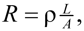
The resistance (R) of a length of wire is given by
 (2)
(2)
where
ρ = resistivity of the medium composing the wire,
L = length,
A = area of the conducting cross section.
Note that if R is expressed in ohms (Ω), the resistivity has the dimensions of ohms multiplied by a unit of length. It is commonly expressed in Ωm but may be given in Ω-cm or Ω-ft. The conductivity (σ) of a material is defined as the reciprocal of its resistivity (ρ). Resistivity is thus seen to be an intrinsic property of a material, in the same sense that density and elastic moduli are intrinsic properties.
In most earth materials, the conduction of electric current takes place virtually entirely in the water occupying the pore spaces or joint openings, since most soil- and rock-forming minerals are essentially nonconductive. Clays and a few other minerals, notably magnetite, specular hematite, carbon, pyrite, and other metallic sulfides, may be found in sufficient concentration to contribute measurably to the conductivity of the soil or rock.
Water, in a pure state, is virtually nonconductive but forms a conductive electrolyte with the presence of chemical salts in solution, and the conductivity is proportional to the salinity. The effect of increasing temperature is to increase the conductivity of the electrolyte. When the pore water freezes, there is an increase in resistivity, perhaps by a factor of 104 or 105, depending on the salinity. However, in soil or rock, this effect is diminished by the fact that the pore water does not all freeze at the same time, and there is usually some unfrozen water present even at temperatures considerably below freezing. The presence of dissolved salts and the adsorption of water on grain surfaces act to reduce the freezing temperature. Even so, electrical resistivity surveys made on frozen ground are likely to encounter difficulties because of the high resistivity of the frozen surface layer and high contact resistance at the electrodes. On the other hand, the effect of freezing on resistivity makes the resistivity method very useful in determining the depth of the frozen layer. It is very helpful in the interpretation of such surveys to have comparison data obtained when the ground is unfrozen.
Since the conduction of current in soil and rock is through the electrolyte contained in the pores, resistivity is governed largely by the porosity, or void ratio, of the material and the geometry of the pores. Pore space may be in the form of intergranular voids, joint or fracture openings, and blind pores, such as bubbles or vugs. Only the interconnected pores effectively contribute to conductivity, and the geometry of the interconnections, or the tortuosity of current pathways, further affects it. The resistivity ρ of a saturated porous material can be expressed as
![]() (3)
(3)
where
F = formation factor,
ρW = resistivity of pore water.
The formation factor is a function only of the properties of the porous medium, primarily the porosity and pore geometry. An empirical relation, Archie's Law, is sometimes used to describe this relationship:
![]() (4)
(4)
where
a and m = empirical constants that depend on the geometry of the pores,
φ = porosity of the material.
Values of a in the range of 0.47 to 2.3 can be found in the literature. The value of m is generally considered to be a function of the kind of cementation present and is reported to vary from 1.3 for completely uncemented soils or sediments to 2.6 for highly cemented rocks, such as dense limestones. Equations 3 and 4 are not usually useful for quantitative interpretation of data from surface electrical surveys but are offered here to help clarify the role of the pore spaces in controlling resistivity.
Bodies of clay or shale generally have lower resistivity than soils or rocks composed of bulky mineral grains. Although the clay particles themselves are nonconductive when dry, the conductivity of pore water in clays is increased by the desorption of exchangeable cations from the clay particle surfaces.
Table 1 shows some typical ranges of resistivity values for manmade materials and natural minerals and rocks, similar to numerous tables found in the literature (van Blaricon 1980; Telford et al. 1976; Keller and Frischknecht 1966). The ranges of values shown are those commonly encountered but do not represent extreme values. It may be inferred from the values listed that the user would expect to find in a typical resistivity survey low resistivities for the soil layers, with underlying bedrock producing higher resistivities. Usually, this will be the case, but the particular conditions of a site may change the resistivity relationships. For example, coarse sand or gravel, if it is dry, may have a resistivity like that of igneous rocks, whereas a layer of weathered rock may be more conductive than the soil overlying it. In any attempt to interpret resistivities in terms of soil types or lithology, consideration should be given to the various factors that affect resistivity.
Table 1. Typical electrical resistivities of earth materials.
|
Material |
Resistivity (Ωm) |
|
Clay |
1-20 |
|
Sand, wet to moist |
20-200 |
|
Shale |
1-500 |
|
Porous limestone |
100-1,000 |
|
Dense limestone |
1,000-1,000,000 |
|
Metamorphic rocks |
50-1,000,000 |
|
Igneous rocks |
100-1,000,000 |
Classification of Electrical Methods
The number of electrical methods used since the first application around 1830 (Parasnis 1962) is truly large; they include self-potential (SP), telluric currents and magnetotellurics, resistivity, equipotential and mise-à-la-masse, electromagnetic (EM), and induced polarization (IP). Because of the large number of methods, there are many ways of classifying them for discussion. One common method is by the type of energy source involved, that is, natural or artificial. Of the methods listed above, the first two are grouped under natural sources and the rest as artificial. Another classification, which will be used here, is to group by whether the data are measured in the time domain or the frequency domain. Only techniques in common use today for solving engineering, geotechnical, and environmental problems will be treated in this discussion, thus omitting telluric current techniques, magnetotellurics, and many of the EM methods.
Time domain methods (often abbreviated as TDEM or TEM) are those in which the magnitude only or magnitude and shape of the received signal is measured. The techniques in this class are discussed under the headings DC resistivity, induced polarization, time-domain electromagnetics, and self-potential. Frequency domain methods (often abbreviated as FDEM or FEM) are those in which the frequency content of the received signal is measured. Generally FDEM methods are continuous source methods, and measurements are made while the source is on. The measurement is of magnitude at a given frequency. Techniques in this class are discussed under the headings of VLF, terrain conductivity, and metal detectors.
Resistivity Methods Versus Electromagnetic Methods
Before discussing the individual methods, it is useful to outline the main differences between the resistivity (including induced polarization) methods and the electromagnetic methods. With resistivity methods, the source consists of electrical current injected into the ground through two electrodes. The transmitted current waveform may be DC, low- frequency sinusoidal (up to about 20 Hz), or rectangular, as in induced polarization surveys with a frequency of about 0.1 Hz. The energizer, therefore, is the electrical current injected into the ground through current electrodes.
With electromagnetic methods, the source most commonly consists of a closed loop of wire in which AC current flows. It can be a small, portable transmitter coil up to 1 m in diameter, in which case there are many turns of wire. Alternately, the source can be a large transmitter loop on the ground, as large as 1 km in diameter. The frequency of the transmitter current can range from about 0.1 to about 10,000 Hz. Instruments commonly used for engineering applications (such as the EM-31, EM-34, and EM-38) use the small, multiturn type of coil and frequencies above 2,500 Hz. Electric current in the transmitter loop generates a magnetic field. The magnetic field is the energizer in electromagnetic methods as compared with electric current in resistivity methods.
In terms of response, with resistivity methods, anomalies result from resistivity contrasts. For example, if a target with a resistivity of 10 Ωm is in a host rock with a resistivity of 100 Ωm, the same anomaly results as if the target had a resistivity of 100 Ωm in a host rock with a resistivity of 1,000 Ωm. In both cases, there is a resistivity contrast of 10. This example holds as long as the transmitter frequency is low enough that there is no appreciable electromagnetic induction in the rocks. With electromagnetic methods, anomalies are due more to absolute resistivity rather than resistivity contrasts. The two examples mentioned previously for resistivity methods would not produce the same anomalies with electromagnetic methods (Klein and Lajoie, 1980).
The pages found under Surface Methods and Borehole Methods are substantially based on a report produced by the United States Department of Transportation:
Wightman, W. E., Jalinoos, F., Sirles, P., and Hanna, K. (2003). "Application of Geophysical Methods to Highway Related Problems." Federal Highway Administration, Central Federal Lands Highway Division, Lakewood, CO, Publication No. FHWA-IF-04-021, September 2003. http://www.cflhd.gov/resources/agm/
