 A newsletter that provides descriptions
and performance data for developments in innovative ground water treatment.
A newsletter that provides descriptions
and performance data for developments in innovative ground water treatment.

Ground Water Currents, June 1998, Issue No. 28
Contents
Dynamic Underground Stripping for Creosote Removal
In Situ Steam Stripping and Bioremediation Used in Shallow Media at Pinellas
Restoration Technology Development for DNAPL in Fractured Bedrock
TSP Releases New Issue Paper on Steam Injection
Dynamic Underground Stripping for Creosote Removal
by Eva Davis, Ph.D., U.S. Environmental Protection Agency, Robert S. Kerr Environmental Research Laboratory
Underground steam injection at depths of 80-100 feet is underway at Southern California Edison’s Visalia, CA, Pole Yard to recover creosote. The injected steam displaces free-phase creosote to extraction wells and increases its volatility and solubility, and thus its recovery, in the aqueous and vapor phases. In addition, the increased temperatures resulting from steam injection enhance in situ oxidation of the creosote components through biological and/or thermal degradation. To date, it is estimated that 80,000 gallons of creosote have been recovered or destroyed since this technology was initiated in May 1997.
Steam injection has been used for enhanced oil recovery since the 1930s. In the late 1980s, Dr. Kent Udell at the University of California at Berkeley pioneered the use of steam injection for soil and aquifer remediation. In partnership with Lawrence Livermore National Laboratories, the process of dynamic underground stripping (DUS) was developed. The DUS process includes steam injection into permeable areas for the physical displacement and volatilization of contaminants and electrical heating of low permeability layers to volatilize contaminants.
DUS is effective for volatile and semivolatile organic contaminants and is capable of recovering contaminants in both the liquid and vapor phases. Electrical resistance tomography is used for near real-time monitoring of the subsurface steam movement and allows daily control of the steam injection process. In addition, it has been found that many contaminants will oxidize thermally at the subsurface temperatures achieved through steam injection.
A total of approximately 270 million pounds of steam, at temperatures of 171-182oC, have been injected into a 2-acre subsurface area at the Visalia site using a cyclic process. Steam is injected through 11 wells that surround the free-phase creosote, and recovered through seven centrally located extraction wells. Initially, the injected steam condenses, and the resulting condensation heats the subsurface. When the subsurface reaches steam temperatures, the steam expands radially from the well, displacing condensed steam and contaminants in front of it. After steam breakthrough at the extraction wells, injection is halted while ground water and vapor extraction continue. The steam zone then collapses, and the water and vapors that had been pushed away from the extraction area are brought back toward the extraction wells for recovery. The lower air phase pressures resulting when steam injection is halted allow increased recovery of contaminants in the vapor phase.
Prior to the initiation of steam injection, a ground-water pump and treat system handling 400 gallons/minute was in place at the Visalia site. Although the pump and treat system reduced the size of the dissolved phase plume effectively during more than 20 years of operation, it recovered less than 10 pounds per week of creosote. Through steam injection, the rate of creosote recovery was increased by more than a factor of 1,000.
Currently, steam injection and the recovery of free-phase creosote is continuing. Planning is underway to install deeper steam injection wells to recover creosote trapped in a low permeability layer below the current injection depth of 100 feet. After recovery of free-phase creosote is complete, ground-water monitoring is expected to continue for two years. During this time, the subsurface will remain at elevated temperatures and in situ oxidation, through both thermal and biological means, is expected to degrade the remaining dissolved phase contaminants.
To date, approximately $11 million have been spent on the steam injection system, and current estimates are that the total cost will be $20 million. This compares favorably with the site record of decision’s estimated cost of $45 million for enhanced bioremediation. For additional information, contact Dr. Eva Davis (U.S. Environmental Protection Agency) at 580-436-8548 or e-mail Davis.Eva@epa.gov, or Craig Eaker (Southern California Edison) at 626-302-8531 or e-mail eakercl@sce.com.
In Situ Steam Stripping and Bioremediation Used in Shallow Media at Pinellas
by Mike Hightower, Sandia National Laboratories
Two field-scale operations focusing on the remediation of shallow soils and ground water were completed recently at the Pinellas Science, Technology, and Research (STAR) Center, formerly the U.S. Department of Energy’s (DOE’s) Pinellas Plant in Largo, FL. A dual-auger rotary steam stripping operation was conducted to reduce areas of high concentrations (500-5,000 parts per million) of volatile organic compounds (VOCs) below a shallow water table located less than 2 feet below ground surface. At more moderate contaminant levels (100-200 parts per million) the potential application of in situ anaerobic bioremediation then could be assessed. In the second technology application, bioremediation capabilities were tested through the addition of nutrients to stimulate in situ anaerobic degradation of chlorinated solvents in the shallow, anaerobic aquifer underlying the site. Both technologies proved effective in treating the site contaminants.
From 1956 to 1994, the Pinellas Plant operations involved manufacturing of neutron generators and other electronic and mechanical components for nuclear weapons. Application of the dual auger rotary steam stripping technology took place in an area of the site that was formerly used as a waste solvent staging, storage, and disposal area, where shallow, saturated soil and ground water were contaminated with high concentrations (500-5,000 parts per million) of VOCs.
The dual auger system used at Pinellas consists of a trackhoe modified to operate two vertical, 35-foot long, hollow kelly bars with 5-foot diameter augers, as shown in Figure 1. Air and/or steam is injected through the hollow kellys while the augers drill into the subsurface, liberating VOC contamination during the churning and mixing of the soil. A large shroud covers the auger hole to capture the VOCs removed by this process for treatment. A catalytic oxidation unit and acid-gas scrubber were used to treat the extracted VOCs.
During the system’s 3-month operating period, 48 auger holes were drilled to depths of approximately 32 feet below land surface, resulting in treatment of approximately 2,000 cubic yards of saturated soil and ground water. Treatment rates varied from 1 to 5 holes/day, or about 5-30 cubic yards/hour, depending on the level of contamination encountered in each hole. Overall, approximately 1,200 total pounds of VOCs were removed from the soil and ground water in the holes that were treated, and contaminant levels generally were reduced by 70-80%. Treatment rate often was limited to prevent the catalyst in the catalytic oxidation unit from overheating from the large quantities of VOCs liberated by the augers. Operational costs for the dual auger system ranged from $50-400/cubic yard of treated soil and ground water, or about $300-500/pound of contaminant removed.
The in situ anaerobic bioremediation demonstration was designed to evaluate the use of nutrient injection in areas of moderate ground-water contaminant concentrations (100-400 parts per million), and to obtain operating and performance data to optimize the design and operation of a full-scale bioremediation system. Preliminary laboratory testing had shown significant promise of using this technique for cost-effective remediation at the site. The pilot was located in an area with total chlorinated contaminant concentrations in ground water ranging from 10 to 400 parts per million, with one monitoring well having concentrations exceeding 2,900 parts per million.
The bioremediation system consisted of three 8-foot deep gravel-filled, surface infiltration trenches and two 240-foot long horizontal wells with 30-foot screened intervals. The horizontal wells, directly underlying and parallel to the middle surface trench, were at 16- and 26-foot depths. The study area was about 45 feet by 45 feet and extended from the surface down to a thick, clay confining layer 30 feet below the surface. Ground water was extracted from the upper horizontal well and recirculated via the surface trenches and the lower horizontal well to create a vertical recirculation cell. Sodium benzoate, sodium lactate, and methanol were added to the recirculated water as nutrients to enhance the degradation of the chlorinated VOCs by the indigenous bacteria.
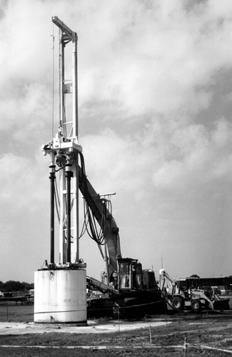
Figure 1: Rotary Steam Stripping at the Pinellas
Plant
During the bioremediation pilot’s six month operating period, ground water was extracted and recirculated at a rate of about 1.5 gallons/minute. Approximately 250,000 gallons of water (about two pore volumes) were circulated during the pilot study. Tracer and nutrient monitoring data indicated that nutrients were delivered to 90% of the central treatment area during operations. Significant declines in total chlorinated VOC concentrations (70-99%) were observed in the wells where nutrient breakthrough was identified. Degradation rates of as high as 1-2 parts/million/day were observed in high concentration areas. Monitoring data showed that the bacterial dechlorination process did not stop at any intermediate compounds and that contaminant reductions to regulatory levels can be obtained.
These technology applications were sponsored by the Innovative Treatment Remediation Demonstration (ITRD) Program coordinated by DOE’s Sandia National Laboratories. The ITRD Program is a joint effort between DOE and EPA to reduce barriers to the use of new technologies. Through the ITRD Program, DOE, EPA, industry, and regulatory agency representatives worked with the Pinellas Environmental Restoration Program on these innovative technology applications.
Cost and performance reports on these two applications are available. For more information, contact Mike Hightower (Sandia National Laboratories) at 505-844-5499, Dave Ingle (Pinellas STAR Center) at 813-541-8943, or the ITRD Web site http://www.em.doe.gov/itrd/.
Restoration Technology Development for DNAPL in Fractured Bedrock
by J. Edward O’Neill, Smithville Phase IV Bedrock Remediation Program
The complexities of removing dense non-aqueous phase liquids (DNAPLs) from fractured bedrock at a former hazardous waste storage and disposal facility in Smithville, Ontario, Canada, have led to the formation of a unique public/community partnership for restoring the site. The Managing Board of Directors of the Smithville Phase IV Bedrock Remediation Program (the Board), formed in 1993, consists of representatives from Ontario’s Ministry of Environment and Energy, the Township of West Lincoln, Ontario, and a public liaison group known as the Chemical Waste Management Liaison Committee. The Board is charged with selecting a preferred remedial alternative for this site.
Recognizing that no technologies have proven effective yet for remediating DNAPLs in fractured carbonate bedrock, the Board developed a 10-step approach for selecting a preferred remedial alternative (Figure 2). Aggressive efforts to solicit community involvement through an active stakeholder working group and extensive outreach mechanisms are incorporated into each step.
Figure 2: Steps in the Decision-Making Process
Chemical Waste Management Limited used this site for operation of a primary waste transfer facility for polychlorinated biphenyls (PCBs) from 1978 to 1980, at which time the U.S. border was closed to shipment of hazardous wastes. The facility’s inventory, consisting of PCBs stored in drums, tanks, and (leaking) tank trucks, filled to capacity and the site became known as Canada’s largest PCB storage area. It is estimated that about 30,000 liters of PCB liquid migrated through the clay overburden into a shallow, bedrock aquifer. This PCB oil, mostly present as undissolved DNAPL, comprises approximately 42% (by weight) PCB, 13% chlorobenzenes, 2% trichloroethylene, and 43% other hydrocarbons.
Currently, the Board is collaborating with the U.S. EPA; the University of Waterloo, Ontario; Environment Canada; McMaster University; and the University of Utah in site characterization efforts through application of an existing fracture flow model (FRAC3DVS). The FRAC3DVS model will be expanded to investigate capture zones in fractured carbonate rocks. In addition to facilitating decision-making for the Smithville site, it is anticipated that these modeling results will create an extensive site characterization data bank that will be useful for remedy selection at other sites with similar geologic conditions.
In 1989, a pump and treat system was installed around the DNAPL plume to control migration of dissolved contaminants. An aquitard of less porous rock appears to have prevented DNAPL from migrating from the shallow aquifer into intermediate and deep aquifers; however, monitoring results indicate that dissolved contaminants are present in the deeper aquifers.
The Board has been using the 10-step decision-making process over the last year and recently has completed Step 4, “Establish Alternatives.” The remedial alternatives identified include one natural attenuation alternative and eight engineered alternatives that potentially are viable for application at this site. The eight engineered alternatives include thermal wells (combined with a ground-water barrier technology); excavation and ex situ treatment; hydromill excavating; ground freezing; permeation grouting; secant piling (megadrilling); extraction wells; and integrated permeation grouting and extraction wells. A comparative evaluation of these nine alternatives (Step 9) is scheduled to occur in late 1998 and early 1999 to identify the preferred alternative(s). All of these technologies suffer from potential adverse effects; however, none has been tested in fractured bedrock. Final selection of the preferred remediation alternative is planned for late 1999.
For more information, contact J. Edward O’Neill (Smithville Phase IV Bedrock Remediation Program) at 905-957-4077, or visit the Web site http://www.niagara.com/sp4/.
TSP Releases New Issue Paper on Steam Injection
In January 1998, EPA’s Technology Support Project (TSP) released an issue paper titled Steam Injection for Soil and Aquifer Remediation. The paper provides basic technical information on the use of steam injection for remediation of soils and aquifers that are contaminated by volatile or semivolatile organic compounds. Topics include the process of steam injection, applicable contaminant and subsurface conditions, general design and equipment considerations, and laboratory and field-scale experimental results. The document can be read or downloaded from the web site http://www.epa.gov/ada/pubs/issue.html.
|
|