![]() A newsletter about soil, sediment, and groundwater characterization and remediation technologies
A newsletter about soil, sediment, and groundwater characterization and remediation technologies
This issue of Technology News and Trends highlights "green remediation," the practice of considering all environmental effects of remedy implementation and incorporating options to maximize the net environmental benefit of cleanup. The applications in this issue demonstrate increased sustainability that can be gained through use of renewable energy sources to power treatment systems or through well-designed biological systems complementing site reuse. Green remediation strategies closely evaluate a cleanup project's water requirements, material consumption, waste generation, ecosystem impacts, and long-term stewardship requirements in addition to energy consumption.
Wind-Driven SVE System Extracts VOCs from Landfill
CLU-IN Resources
EPA's Office of Superfund Remediation and Technology Innovation recently released a Green Remediation web site on CLU-IN. "GR Web" explains basic principles and objectives of green remediation and outlines best management practices for reducing the environmental footprint of cleanup actions. Over coming months, the site will expand to describe more details on best practices and serve as a clearinghouse for technical materials, decision-making tools, site-specific case studies, and information on related events and new information products. Visit GR Web at http://clu-in.org/greenremediation/. Information on related "Eco-Tools" for returning disturbed lands to ecological reuse is available at http://www.clu-in.org/
ecotools/index.cfm.
An innovative soil vapor extraction (SVE) system has operated at the former Ferdula Landfill site in Frankfort, NY, for the past 10 years. The system relies on wind-driven vacuum processes rather than electrically powered air blowers to extract volatile organic compounds (VOCs) from the landfill. After a two-year trial beginning in 1998, the New York State Department of Environmental Conservation (NYSDEC) approved long-term use of the SVE system to address VOC-contaminated soil serving as a contaminant source within the landfill. Soil-gas monitoring indicates that concentrations of contaminants of concern, primarily toluene and trichloroethene (TCE), have decreased 91-94% since implementing system upgrades in late 2001.
The landfill received industrial waste such as chlorinated and non-chlorinated solvents generated during gun manufacturing at the nearby Remington Arms Company. Wastes from the wood finishing and metal cleaning processes were disposed at the landfill from approximately 1967 to 1975. Subsurface soil consists of 2-10 feet of a lacustrine sand underlain by a 75-foot-thick lacustrine silt and clay unit with fine seams of sand. Ground water is encountered at a depth of 5-6 feet.
In 1996, the landfill was closed and covered with a conventionally engineered cap constructed of clay and a synthetic membrane. As a second containment remedy, an upgradient diversion system comprising a bentonite slurry wall and underdrain was installed to divert clean ground water away from the site, thereby reducing the amount of leachate requiring treatment. Following downgradient collection, leachate is discharged to the county wastewater treatment system.
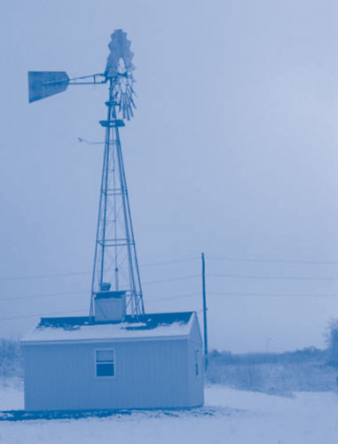
The SVE system was designed to remove VOCs from the unsaturated portion of the 1.8-acre landfill. The system employs a single windmill to create a vacuum that extracts the VOCs for aboveground carbon treatment (Figure 1). The windmill's 12-ft blades reciprocate a single 10-in air cylinder fitted with check valves that enable each intake stroke to draw a vacuum from the landfill vents. In turn, the cylinder intake piping is attached to a network of nine gas vents on the landfill cap. Check valves on both ends of the cylinder allow a vacuum to be generated during each intake cycle (both up and down strokes of the windmill), producing about 85 ft3/hr/mph of vacuum for each mile of wind speed per hour. Each cylinder exhaust stroke pushes the extracted air through carbon canisters before emission at the top of a 40-ft tower.
The windmill operates at all times with winds of 3-20 mph. During winds exceeding 20 mph, a safety feature automatically furls the mill away from the wind and applies a brake to suspend operations. In contrast to continuous operation of air blowers used in conventional SVE systems, wind intermittency inherently provides the pulsed effect typically found to be more effective in venting operations.
System upgrades were implemented after the two-year trial operation to increase the rate of VOC extraction. The area of venting influence was expanded by installing six additional vents to supplement the original three vents. In addition, windmill performance during low wind (< 5 mph) was improved by replacing the original steel blades with aluminum blades as well as the original four bronze bearings with steel roller bearings. This reduction in rotating mass and bearing friction increased operational intermittency of the system 50-90% while maintaining a pulsed effect and increasing the rate of VOC extraction more than 25%. Remote data collection systems also were installed to allow for continuous monitoring.
Soil-gas sampling showed that total VOC concentrations decreased from over 2,000 mg/m3 in 2002 to approximately 175 mg/m3 in 2007. Toluene concentrations in soil gas decreased from an estimated 1,400 mg/m3 in 2002 to 90 mg/m3 in 2007, and TCE concentrations decreased from 200 mg/m3 to 56 mg/m3 in the same period. Since operations began, approximately 1,500 pounds of total VOC mass have been removed. Treatment emissions have consistently met New York state standards for air quality.
The SVE system and auxiliary equipment require no electricity and are not tied to the utility grid. Avoidance of electricity consumption provided a one-year payback for the $14,000 cost of windmill equipment and installation. Project construction costs totaled approximately $40,000, including $23,000 for the building housing the data collection and treatment systems. In contrast, capital cost for a conventional blower-driven SVE system large enough to achieve the comparable rate of VOC removal was estimated at nearly $500,000.
Differences in operation and maintenance (O&M) costs also are significant. Annual O&M for the wind-driven extraction system, primarily for oil changes and parts replacement associated with the windmill, average below $500. Thirty-year O&M costs for a conventional SVE system using a 25-hp air blower were estimated at $75,000 each year, including $15,000 for 164 MWh of electricity.
Community impacts from the windmill-powered system are negligible compared to a traditional system, which would have required a larger building and generated continuous noise impacting residences within 50 feet of the site. Situated on the highest point of the property, the windmill and small treatment building blend well with the local farming community.
The SVE system will operate for at least five more years, depending on continually high rates of VOC extraction, or possibly up to 30 years in support of long-term contaminant containment provided by the landfill and ground-water diversion system. Based on these results, NYSDEC is showcasing the project as an effective, efficient, and sustainable strategy for source removal when combined with long-term containment actions.
Contributed by Peter Ouderkirk, NYSDEC (psouderk@gw.dec.state.ny.us or 315-785-2513) and Sathya Yalvigi, DuPont (sathya.v.yalvigi@usa.dupont.com or 302-892-8035)
Integrated Solar and Wind Energy Powers Oil Recovery System
Recovery of free-product petroleum at the former St. Croix Alumina (SCA) site in Kingshill on St. Croix, VI, is addressing ground-water contamination caused by past releases of fuel and refined petroleum at SCA. The oil recovery system employs wind-driven turbine compressors (WTCs), wind-driven electric generators (WEGs), and photovoltaic (PV) panels to power pneumatic and electric submersible pumps. By the end of 2007, the system had recovered approximately 243,000 gallons of free-product oil, which is 21% of the 1,136,000 gallons estimated to have originally been released. SCA operates the project under a RCRA consent order.
In 1994, EPA became aware of a subsurface oil plume in the SCA vicinity, which was later shown by chromatographic analysis to be caused by co-mingled petroleum products released between 1978 and 1991. In addition to a light non-aqueous phase liquid (LNAPL) plume floating on ground water in the Kingshill Aquifer and on perched ground water, dissolved-phase petroleum hydrocarbon constituents were present in ground water. Although ground water is not utilized at the SCA facility, the Kingshill Aquifer is used upgradient of the facility and elsewhere on the island with less saline conditions. Consequently, the Kingshill Aquifer is an important source of drinking water in some parts of St. Croix.
Wind resource data from the nearby St. Croix airport showed that the site was well suited for wind energy applications. Oil recovery began in 2002 using four WTCs to drive pneumatic total-fluid pumps in six recovery wells. Recovered oil and co-mingled ground water are pumped to a separation tank where oil and water are separated via gravity separation. The oil then is reclaimed and used as feedstock at an adjacent petroleum refinery, as permitted under RCRA, and the water is transferred to a permitted wastewater treatment system prior to discharge to the Caribbean Sea.
Each WTC is powered by a windmill with 4.3-ft blades that begin rotating at a wind speed of 4 mph. When wind speed exceeds 30 mph, the blades furl and turn out of the wind. The air compressor is located directly behind the windmill, on a hinged tower. For maintenance or occasional hurricane protection, the combined blade/compressor unit can be lowered to the ground. Each WTC is designed to generate approximately 45 psi of operating pressure.
A 165-W solar panel array was installed in 2003 to provide electricity for an enhanced fluid-gathering system. In 2006, two WEGs were installed to supplement power for electric submersible total-fluid pumps that were installed in several wells to increase oil recovery by the four WTCs. Two additional WEGs (for a total of four WEGs) and an additional PV array (220 W) were installed the following spring to power four new recovery wells for enhanced hydrocarbon recovery (Figure 2).

In November of last year, a compressed air "makeup" line was added to supplement the air from the WTCs and to maintain a continuous 55-psi operating pressure in the pneumatic recovery pumps when the WTCs are not providing sufficient air pressure. To date, electricity from the utility grid still is not required for the recovery pumps or to collect and transport the recovered total fluids to the separation tanks.
The volume of free-product oil recovered during the second half of 2007, reflecting the recent system upgrades, averaged 91.5 gal/day. During that period, the recovery system employed five pneumatic total-fluid submersible pumps and five electrically powered total-fluid submersible pumps. The submersible pumps recover both free product and ground water, and enhance the ground-water gradient to facilitate capture of free product away from the well bore. Oil "skimmer" pumps capture the oil layer in the well bore but do not create an enhanced gradient for oil to move to the well bore. Semi-annual fluid gauging and analysis of ground-water samples from nine monitoring wells around the perimeter of the plume indicate that both the LNAPL and dissolved constituent plumes are not migrating and remain on the SCA site.
This treatment design was selected due to the absence of onsite electricity upon project startup. SCA estimates that the system's capital costs (including installation of WTCs, WEGs, and PV panels) total nearly $40,000, approximately half the cost to connect to the power grid. The WTCs are no longer manufactured; as a result, future upgrades may include replacement of the WTCs due to unavailability of replacement parts, or custom fabrication of replacement parts.
Contributed by Tim Gordon, EPA Region 2 (gordon.timothy@epa.gov or 212-637-4167)
Engineered Wetland Removes Subsurface Hydrocarbons While Providing Beneficial Reuse
British Petroleum (BP) is operating an engineered wetland to treat petroleum-contaminated ground water at a 300-acre site in Casper, WY. Release of petroleum products during refinery operations from 1908 until 1991 resulted in significant petroleum hydrocarbon contamination. Over 44,000 yd3 of LNAPL were removed by dual-phase recovery wells and oil/water separators constructed in 1981, but additional cleanup measures were needed to address dissolved-phase contaminants. Augmented by a cascading aeration system, the engineered wetland is achieving non-detect concentrations of target compounds such as benzene, toluene, ethylbenzene, and xylenes (BTEX) while allowing concurrent reuse of the property for commercial and recreational purposes.
In 1998, BP and the City of Casper agreed to a cleanup strategy accommodating redevelopment of the site, including a golf course, office park, riverfront trails, and a whitewater kayak course. The plan involved construction of an engineered wetland capable of treating up to 11,000 m3/day of gasoline-contaminated ground water for up to 100 years while blending into the golf course. Designs were initiated in 2000, pilot-scale wetland tests were begun in 2001, and construction of the full-scale wetlands project was completed in 2003.
Maximum concentrations of dissolved-phase hydrocarbons included 330 mg/L benzene and 530 mg/L total BTEX. The site is located in alluvial sand and silt deposits along the floodplain of the North Platte River. Fluctuations in the river�s water level cause the water table to fluctuate within the surficial aquifer, creating a "smear zone" due to remaining LNAPL. The resulting large mass of petroleum hydrocarbons sorbed to the aquifer matrix gradually de-sorbs and dissolves into the water, causing elevated hydrocarbon concentrations.
Refinery demolition involved excavating and recycling more than 200 miles of underground pipes and recovery and onsite crushing of more than 300,000 tons of foundation concrete. The concrete was reused as aggregate for the wetland treatment system. Construction involved grading of more than 1 million yd3 of soil for the golf course and installation of more than 60 dual-phase recovery wells feeding the ground-water treatment system.
A five-month pilot test was conducted to refine the final design and establish site-specific parameters for contaminant degradation. Test results indicated that potential iron fouling of the wetland media could be addressed by including a cascade aeration system to oxidize iron and a surface-flow wetland to precipitate it. Testing under both aerated and non-aerated conditions demonstrated that ground-water aeration could degrade recalcitrant compounds 45% more effectively, based on the increase in first-order rate constants.
Scaling up from the pilot system required a 1,200-fold increase in reactor volume. Two center-feed, radial-flow treatment beds were constructed using crushed foundation concrete as the subsurface flow-engineered wetland medium. This configuration maximized flow distribution at a rate of up to 6,000 m3/day. One wetland is 360 feet in diameter, and the second is 65% smaller due to space constraints. To withstand winter temperatures as low as -35°F, the cells were insulated with a 6-inch mulch layer. Emergent facultative wetland plants such as bulrushes, switchgrass, and cordgrass were planted in each of the four treatment cells of both wetlands.
After first passing through an oil-water separator to remove any remaining free product, ground water is pumped from the recovery wells to an aboveground �forced bed� cascade aerator that transfers atmospheric oxygen to the ground water, thereby enhancing contaminant volatilization and oxidizing ferrous iron (Figure 3). Off-gas from the cascade aerator is routed to a soil-matrix biofilter to control potential air emissions of BTEX.
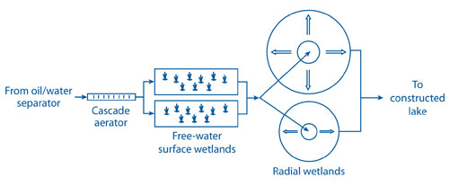
The aerated fluid travels through 60 feet of pipe 3 feet below ground surface to one of two free-water surface wetlands operating in parallel. Residence time in the free-water surface wetlands is approximately 0.5 days. From the surface wetlands, water finally passes through additional subsurface pipes to the center of each subsurface radial wetland, where it radiates under natural hydraulic conditions toward the perimeter of four wedge-shaped treatment zones for additional biodegradation and phytoremediation (including phytovolatilization). Aeration pipes are flushed periodically with citric acid to remove mineral deposits that potentially interfere with air delivery and encourage algae growth after routine fertilization of adjacent golf course turf.
Since full-scale operation began in May 2003, hydraulic loading of the system has averaged 2,600 m3/day (700,000 gal/day). Concentrations of target contaminants in ground-water samples collected from the aerator effluent show benzene and total BTEX concentrations approximately 50% lower than in aerator influent. Concentrations in wetland effluent are below detectable limits prior to discharge into Soda Lake, a basin created by former refinery effluent discharge.
The engineered wetland was selected over other in-situ biological strategies, such as bioremediation or phytoremediation, due to the need to control hydraulic gradient. Construction costs totaling $3.4 million saved an estimated $12.5 million compared to pumping and treatment using stripping towers and activated carbon. O&M consists primarily of sampling, monitoring, and maintenance of the recovery well system.
The Wyoming Oil and Gas Conservation Commission became the anchor tenant of the new office park in March 2004, ten months after the full-scale wetland system began operating. The golf course and other recreational facilities were completed in 2005 as surface features of the wetlands continued to blend with the community (Figure 4).

Contributed by Vickie Meredith, Wyoming Department of Environmental Quality (vmered@state.wy.us or 307-335-6948) and Scott Wallace, Jacques Whitford NAWE, Inc. (scott.wallace@jacqueswhitford.com or 651-255-5050) or 415-972-3158).
Mobile Systems Provide Solar Energy in Northern Climates
The Department of Transportation for Alberta, Canada, is examining innovative strategies to resolve environmental issues in remote areas of the province. Portable units for harnessing solar energy have been demonstrated over the past five years as a viable method for generating the electricity needed to drive remediation systems at several sites in western Canada. The typical mobile system consists of a 21-ft trailer holding a 2-kW PV array and 1,600-amp/hr storage battery used to power, as needed, a 100-psi air compressor, pneumatic pumps, and air blowers over short durations.
Applications indicate that solar energy availability typical to the climate of southern Alberta (6-8 hours during summer and 4-6 hours in winter) is sufficient to power the low to moderate electricity demands and seasonal work often involved in remote cleanups. Through use of the storage battery, however, ample electricity could be withdrawn for systems requiring 24-hour operation. Mobile solar systems were deployed in western Canada to power equipment such as:
- Submersible pumps for dewatering and product skimming at a hydrocarbon-impacted site in Beaver River, BC, from July 2002 to December 2004 (Figure 5). Use of the full 2-kW PV array avoided need for a typically high-maintenance diesel generator consuming a large volume of fuel, or alternate installation of electricity lines extending to the utility grid at an infeasible cost. Successful hydrocarbon recovery prompted plans to install a permanent solar system to fully remediate and reclaim the site.
- An integral 2-hp blower providing air flow of 250 cfm for SVE addressing residual hydrocarbons from a pipeline break at Rocky Mountain House air base from May to September 2006. Solar energy provided sufficient power to enable the SVE system to increase volatilization and promote biodegradation of hydrocarbons, while eliminating the need for routine maintenance and frequent refuelling of diesel generators. Over the five months of operations, hydrocarbon levels in all wellheads were reduced from concentrations more than double the "lowest effect level" (LEL) targeted by the Alberta Ministry of the Environment to less than 10% of the LEL.

The mobile unit's existing 5-kW generator for auxiliary power (when insufficient solar energy is available to provide constant battery charge) burns natural gas at a rate of approximately 0.6 m3/hr. Diesel generators becoming available now offer the "autostart" compatibility needed in these applications, at an estimated fuel consumption rate of 1.3 gal/kWh. Diesel cost for transfer of the mobile unit is estimated at approximately $0.80/mile, or approximately $200 for a typical distance of 250 miles. Rental cost for the unit depends on deployment duration but typically ranges from $1,500 to $1,800 each month.
The 2-kW PV array is estimated to produce approximately 3,650 kWh of electricity annually in 24-volt direct current, 115-volt alternating current, or 240-volt alternating current. Generating the same amount of power with an electricity generator is estimated to produce 512 kg of carbon equivalent or an estimated 12 metric tons of carbon over the typical 25-year lifespan of PV units.
Contributed by Fred Bowker, Ministry of Transportation/Alberta (fred.bowker@gov.ab.ca or 780-415-1263) and Stuart Torr, Worley Parsons Komex (stuart.torr@worleyparsons.com or 403-247-0200).
