Bioremediation
Anaerobic Bioremediation (Direct)
- Overview
- Aerobic Bioremediation (Direct)
- Anaerobic Bioremediation (Direct)
- Cometabolic Aerobic and Anaerobic Bioremediation
- Training
Overview
In anaerobic conditions, microorganisms will ultimately metabolize organic contaminants to methane, limited amounts of carbon dioxide, and trace amounts of hydrogen gas. In anaerobic reactions, bacteria gain energy and grow as an atom on a contaminant is replaced with hydrogen (AFCEE). Anaerobicmetabolism encompasses many processes including fermentation, methanogenesis, reductive dechlorination, sulfate- and iron-reducing activities, and denitrification. Depending on the contaminant of concern, a subset of these activities may occur. In anaerobic metabolism, nitrate, sulfate, carbon dioxide, oxidized metals, or organic compounds, such as chlorinated hydrocarbons, may replace oxygen as the electron acceptor (EPA 2006). Hydrogen used in the reaction typically is supplied indirectly through the fermentation of organic substrates (EPA 2000).
In general, anaerobic conditions are used to degrade highly halogenated contaminants, though some petroleum hydrocarbons may also be biodegraded anaerobically. The halogenated compound, typically a chlorinated solvent such as tetrachloroethene (PCE), trichloroethene (TCE), 1,1,1-trichloroethane (TCA), carbon tetrachloride (CT), chloroform (CF), and methylene chloride or their degradation products dichloroethene (DCE), vinyl chloride (VC), dichloroethane (DCA), and chloroethane serves as the electron acceptor while hydrogen serves as the direct electron donor (EPA 2000). Chlorinated solvents can exist and migrate in multiple phases depending on how they were released and the site conditions present. These include a vapor phase in unsaturated soils, dissolved phase in groundwater, and non-aqueous phase liquids (NAPL) in the subsurface. Most chlorinated solvents are denser than water and hydrophobic. (ITRC 1999).
During anaerobic biodegradation of chlorinated compounds, sequential removal of chloride ions is generally observed. Figure 1 demonstrates the dechlorination of PCE to TCE to cis-DCE or trans-DCE to VC to the final degradation product, ethene. In this reaction, hydrogen, the electron donor, is oxidized while the chlorinated ethene, the electron acceptor, is reduced. Hydrogen is generally the most important electron donor for anaerobic dechlorination (Parsons 2004).
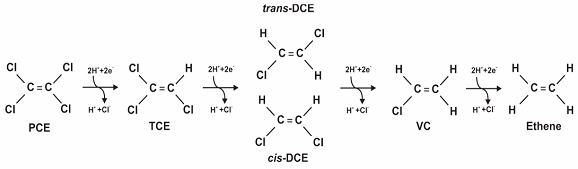
Figure 1. Dechlorination of PCE (Source: Parsons 2004).
The anaerobic reductive dechlorination of the more highly chlorinated (more oxidized) chlorinated hydrocarbons, such as PCE and TCE, occurs more readily than the dechlorination of chlorinated hydrocarbons that already are somewhat reduced (less oxidized), such as DCE and VC. Therefore, it is important to determine as part of the planning stage that Dehalococcoides or other species capable of completely reducing PCE or TCE to ethene are present and are of sufficient quantity to ensure the process does not stop at DCE/VC and allow their build up in the subsurface. If necessary, the site can be bioaugmented with Dehalococcoides Ethenogenes cultures to enable or accelerate degradation to ethene.
Most applications of anaerobic bioremediation occur in situ rather than ex situ. Ex situ technologies include bioreactors and constructed treatment wetlands—which are also used for ex situ aerobic bioremediation. Periodic or permanent saturation of wetland areas leads to anaerobic conditions in the upper portion of the soil where wetland biogeochemical processes typically occur; plants used in constructed wetlands are typically those that are tolerant of anaerobic environments for a portion of the growing season (ITRC 2003). The CLU-IN web page on Phytotechnologies contains more information on how constructed treatment wetlands can be used to clean up contamination.
Jump to a Subsection
In Situ |
Technology Design |
Performance Monitoring
|
In Situ
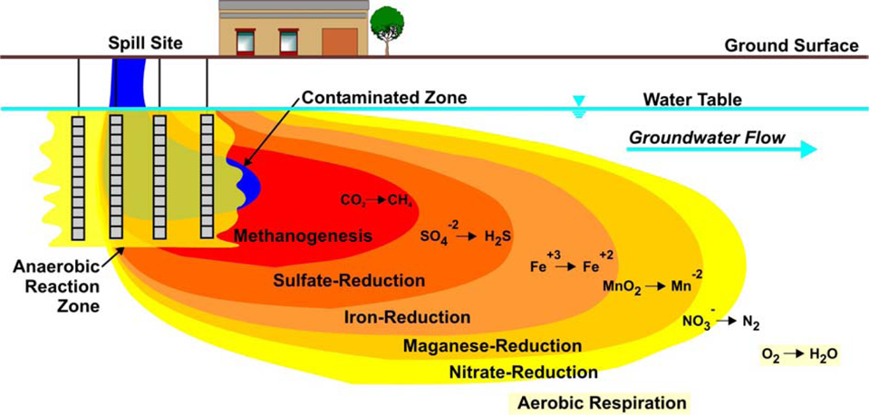
The most frequently used in situ bioremediation technique is enhanced reductive dechlorination that consists of the addition of organic substrates (electron donors) to ensure highly reducing conditions and to provide the hydrogen needed by dechlorinating organisms (ITRC 2005), which can be used for dissolved phase contaminants, DNAPL, and DNAPL source zones. In some cases, the addition of selected organisms (bioaugmentation) can be used as well (ITRC 2008). Figure 2 provides an example of the distinct zones that are established after the addition of anorganic substrate to the source area:
![]()
Figure 2. Anaerobic microbes use electron acceptors in preferential order: nitrate, manganese, ferric iron oxyhydroxides, sulfate, and carbon dioxide (Source: Parsons 2004).
Most chlorinated solvents are DNAPLs; their properties make investigation and remediation difficult (ITRC 1999). In situ bioremediation does not work directly on free-phase DNAPL, instead relying on degradation and solubilization processes that occur near the water-DNAPL interface. In situ bioremediation technology and injection of electron donors can enhance the dissolution and desorption of non-aqueous-phase contaminants to the aqueous phase in which they can be degraded by the microbial population (ITRC 2008).
Guidance on bioremediation of DNAPLs can be found in the ITRC Technical/Regulatory Guidance documents on In Situ Bioremediation of Chlorinated Ethene: DNAPL Source Zones![]() (2008) and Overview of In Situ Bioremediation of Chlorinated Ethene DNAPL Source Zones
(2008) and Overview of In Situ Bioremediation of Chlorinated Ethene DNAPL Source Zones![]() (2005), as well as the Parsons (2004) document on Principles and Practices of Enhanced Anaerobic Bioremediation of Chlorinated Solvents
(2005), as well as the Parsons (2004) document on Principles and Practices of Enhanced Anaerobic Bioremediation of Chlorinated Solvents![]() . The CLU-IN web page on Dense Nonaqueous Phase Liquids (DNAPL): Treatment Technologies contains more information and additional references for DNAPL treatment, including bioremediation.
. The CLU-IN web page on Dense Nonaqueous Phase Liquids (DNAPL): Treatment Technologies contains more information and additional references for DNAPL treatment, including bioremediation.
Addition of organic substrates — Many different substrates can be used to stimulate anaerobic biodegradation. However, the organic substrate(s) selected should be appropriate based on the biogeochemistry and hydrology of the site (Parsons 2004). Common substrate types include soluble substrates (lactate, molasses), slow-release substrates (vegetable oil, emulsified vegetable oil (EVO), Hydrogen Release Compound [HRC®]), and solid substrates such as mulch and compost (Henry 2010a).
|
Substrate |
Product/Vendor |
Typical Delivery Technique |
Form of Application |
Injection Frequency |
|---|---|---|---|---|
|
Common Soluble Substrates |
||||
|
Sodium lactate, lactic acid |
|
|
Diluted in water |
Continuous over short periods to monthly |
|
Propionate and butyrate |
|
|
Acids or salts diluted in water |
Continuous over short periods to monthly |
|
Methanol and ethanol |
|
|
Diluted in water |
Continuous over short periods to weekly |
|
Sodium benzoate |
|
|
Dissolved in water |
Continuous over short periods to monthly |
|
Molasses, high fructose corn syrup |
|
|
Dissolved in water |
Daily to quarterly |
|
Slow-Release Substrates |
||||
|
Hydrogen Releasing Compound® (HRC®) Products |
|
|
Straight injection of product |
Every 1 (HRC®) to 3 (HRC-X® [extended release formula]) years; one-time application possible |
|
Vegetable oils |
|
|
Straight oil injection with water push or oil in water emulsions (high oil [>20%] to water content) |
One-time application (typically) |
|
Vegetable oil emulsions |
|
|
Low oil content (<10%) microemulsions suspended in water |
Every 2-3 years (typically); one-time application possible |
|
Chitin |
|
|
Solid or slurry |
Every 1-2 years potentially; not well-known |
|
Whey |
|
|
Dry or dissolved in water or slurry; dry product more commonly used |
Monthly to yearly |
|
Solid Substrates |
||||
|
Mulch and compost |
|
|
Trenches, excavations, or surface amendments |
One-time application (typically) |
|
Chitin (solid) |
|
|
Solid amendment |
|
|
Other |
||||
|
Zero valent iron (ZVI) and organic substrate |
|
|
Varies depending on vendor |
Varies |
|
Emulsified ZVI |
|
|
Nanoscale or microscale iron suspended in an oil- water emulsion. |
|
|
Hydrogen |
|
|
Gas injection |
Daily to weekly pulsed injection |
|
Humic acids |
|
|
Dissolved in water |
Potentially yearly or semi-annually; not well-known |
Adapted from Parsons![]() (2004) and Henry
(2004) and Henry![]() (2010b)
(2010b)
Below is a list of substrate-specific guidance for several commonly used organic substrates for enhanced in situ anaerobic bioremediation.
 Protocol for Enhanced In Situ Bioremediation Using Emulsified Edible Oil
Robert Borden, Solutions-IES.
Environmental Security Technology Certification Program, 100 pp, May 2006.- Protocol For In Situ Bioremediation of Chlorinated Solvents Using Edible Oil
Air Force Center for Engineering and the Environment (AFCEE), 2007.
This document follows directly from the content of Principles and Practices of Enhanced Anaerobic Bioremediation of Chlorinated Solvents but focuses on the application of pure edible oil and edible oil emulsions to provide a long-lasting organic substrate for enhanced in situ anaerobic bioremediation of chlorinated solvents.
 - Technical Protocol for Using Soluble Carbohydrates to Enhance Reductive Dechlorination of Chlorinated Aliphatic Hydrocarbons
Suthersan, S.S., C.C. Lutes, P.L. Palmer, F. Lenzo, F.C. Payne, D.S. Liles, and J. Burdick.
Environmental Security Technology Certification Program (ESTCP). 173 pp, 2002.
This protocol provides guidance for successful site selection and application of enhanced reductive dechlorination (ERD) technology for remediation of chlorinated hydrocarbons through stimulation by soluble carbohydrates. The ERD technology (patented by ARCADIS) stimulates indigenous microbiological organisms through the engineered addition of electron donors (e.g., molasses, whey, high-fructose corn syrup, lactate, butyrate, benzoate) that contain degradable organic carbon sources.
The quantity of substrate delivered during anaerobic bioremediation is an important component of system design. Excessive amounts of substrate may lead to uncontrolled fermentation reactions, such as decreased pH, secondary water quality degradation, and inefficient use of available substrate by microorganisms. Insufficient substrate, on the other hand, can lead to non-uniform substrate delivery or uneven mixing, and incomplete biodegradation of the contaminants of concern. For guidance on substrate loading rates, refer to the Henry (2010a) Final Report: Loading Rates and Impacts of Substrate Delivery for Enhanced Anaerobic Bioremediation![]() , Henry (2010b) Cost and Performance Report: Loading Rate and Impacts of Substrate Delivery for Enhanced Anaerobic Bioremediation
, Henry (2010b) Cost and Performance Report: Loading Rate and Impacts of Substrate Delivery for Enhanced Anaerobic Bioremediation![]() , and the Henry (2010c) Loading Rates and Impacts of Substrate Delivery for Enhanced Anaerobic Bioremediation: Addendum to the Principles and Practices Manual.
, and the Henry (2010c) Loading Rates and Impacts of Substrate Delivery for Enhanced Anaerobic Bioremediation: Addendum to the Principles and Practices Manual.
Bioaugmentation—bioaugmentation may be considered at a site with an insufficient population of microorganisms, or an insufficiently active population, to perform complete biodegradation of the contaminants of concern. Bioaugmentation is performed by injection of non-native microorganisms into the substrate (Parsons 2004). For guidance on bioaugmentation, refer to the Environmental Security Technology Certification Program documents on Bioaugmentation of Chlorinated Solvents![]() (2005) and Applying Bioaugmentation to Treat DNAPL Sources in Fractured Rock
(2005) and Applying Bioaugmentation to Treat DNAPL Sources in Fractured Rock![]() (2017).
(2017).
Nutrients and other amendments—the subsurface may contain adequate amounts of nutrients to sustain the microbial population. However, rapid microbial growth in response to organic substrate addition can create an additional nutrient demand. Nutrients generally added include nitrogen, phosphorus, and yeast extracts (Parsons 2004).
Amendments to treatment area geochemistry may also be needed to enhance bioremediation—typically these are pH buffering agents for the treatment zone. Anaerobic biodegradation of substances to metabolic acids may significantly lower the pH (Parsons 2004)—for example, the production of H+ ions during reductive dechlorination or the production of volatile fatty acids from electron donor fermentation tends to decrease the pH of groundwater (ITRC 2008). A pH below 5 or 4 standard units could inhibit microbial growth, particularly sulfate-reducers, methanogens, and some dechlorinating microbes (Parsons 2004) (optimum pH for bioremediation is between 6 and 8 standard units [ICSS 2006]). Sodium bicarbonate is a typical pH buffering compound used, but it is a relatively weak buffer and may be most appropriate for bioremediation applications where soluble substrates are injected frequently. Stronger and more persistent buffering compounds such as magnesium hydroxide or sodium phosphates may be used for bioremediation applications where slow-release substrates are used (Henry 2010b).
Technology Design
Substrates, amendments, or microorganisms can be delivered by a number of methods:
- Direct injection—substrate may be injected directly through probe rods or injection wells. Probe rod injection is commonly used for slow-release and soluble substrates (Parsons 2004). Microbes, nutrients, oxidants, or reductants are added directly into the aquifer at injection points or directly into the soil. In groundwater scenarios, the natural flow of the groundwater generally is not impeded by injection but is monitored to determine that the radius of influence of the amendments and substrates is adequate and the degradation of the contaminants and their daughter products is completed within an acceptable distance from the source (EPA 2000). There are two methods typically used for direct injection in bioremediation systems:
- Direct push—this method is often used in sites with shallow groundwater (<50ft below ground surface) in unconsolidated formations. This method does not involve the use of permanent wells and therefore is most practical when long-lasting substrates, such as vegetable oil emulsions or HRC® products, are used (Parsons 2004).
- Permanent injection wells—this method is generally used with soluble substrates. Permanent injection wells are installed when multiple or continuous injections are planned, or when soil lithology or depth make direct-push technology impractical (Parsons 2004).
- Other delivery techniques such as hydraulic or pneumatic fracturing can be used to enhance the spread of amendments and contact with contaminants.
(2009), which provides information on general tools and best practices to be used during the planning, design, and field implementation phases of in situ remediation projects that involve the use of reagents. - Anaerobic bioventing—while aerobic bioventing is useful in degrading many hydrocarbons, aerobic treatment is not effective for many halogenated compounds. Anaerobic bioventing is used for soil contamination and uses the same type of gas delivery system as aerobic bioventing, but instead of injecting air, nitrogen and electron donors, such as hydrogen and carbon dioxide are used. The nitrogen and electron donors displace the soil oxygen thereby facilitating microbial dehalogenation. However, anaerobic bioventing may lead to the mobilization of volatile and semivolatile organic compounds that are not anaerobically degradable (EPA 2006). Depending upon the type of bioventing system being employed, these can require treatment. For further guidance on anaerobic bioventing, refer to the EPA Engineering Forum Issue Paper: In Situ Treatment Technologies for Contaminated Soil, as well as the Battelle Memorial Institute Principles and Practices of Bioventing (Leeson and Hinchee 1996), Volume I and Volume II.
- Recirculation—this method is used to recirculate substrate or other amendments in contaminated groundwater. Contaminated groundwater from the site is extracted and amendments are added. The water is then reinjected into the subsurface, generally upgradient of the target zone (ITRC 2008). The most common recirculation systems consist of a closed network of injection and extraction wells (Parsons 2004). For more information on recirculation, refer to Cunningham et al. (2004) Hydraulics of Recirculating Well Pairs for Ground Water Remediation and ITRC In Situ Bioremediation of Chlorinated Ethene: DNAPL Source Zones (2008) has a discussion on configurations of recirculation systems.
- Permeable reactive barriers (PRBs) and treatment zones—this method involves creating an active bioremediation zone by methods such as backfilling a trench with nutrient-, oxidant-, or reductant-rich materials, or by creating a curtain of active bioremediation zone through direct injection or groundwater recirculation at the toe of a plume. PRBs and treatment zones contain a contaminant plume by treating only groundwater that passes through it (EPA 2000). For a bibliography of guidance documents for using PRBs and treatment zones, refer to the CLU-IN web page on Permeable Reactive Barriers. The ITRC updated technical/regulatory guidance: Permeable Reactive Barrier: Technology Update (2011) has additional information.
Performance Monitoring
The table below provides a menu of performance monitoring parameters for chemicals that degrade under anaerobic conditions. It also describes what each parameter is used for and a recommended frequency of analysis. To promote biodegradation of these chemicals in groundwater, it often is necessary to provide an amendment that first enhances aerobic growth, which depletes the oxygen supply, and then acts as an electron donor to stimulate anaerobic activity and the destruction of the target chemicals (ITRC 2008). For the amendment to be completely effective, it needs to permeate the entire affected subsurface area. Downgradient pumping can be used to assist in spreading the amendment, but it is subject to preferential flow patterns. Performance monitoring with geophysical techniques, such as cross-borehole radar and electrical resistivity tomography, have been used to identify potential amendment bypass areas that might need special attention. Electron donor tracers will not be needed for MNA.
Remedial progress or success with source zone mass removal also can be estimated using flux techniques and tracers. For nonspecific performance monitoring techniques that might be useful, see Remediation Measurement Tools.
|
Performance Parameter |
Method |
Data Use |
Performance Expectation |
Recommended Frequency of Analysis |
|
Chemicals of Concern (CoCs) |
EPA SW-846: 8260B (VOC) or 8270D (SVOC) (laboratory) Field gas chromatography (GC) or GC/mass spectroscopy (MS) |
Used to determine the regulatory compliance for CoCs, the values by which success of the remediation system will be measured. |
CoCs and degradation products typically are expected to decline to below regulatory compliance levels within the treatment zone after substrate addition. |
Baseline and recommended for each groundwater sampling round. |
|
Methane, Ethane, Ethene |
EPA SW-846: 5021A Robert S. Kerr Laboratory RSK-175 SOP followed by GC or GC/MS |
Elevated levels of methane indicate fermentation is occurring in a highly anaerobic environment and that reducing conditions are appropriate for anaerobic degradation. For chlorinated aliphatic hydrocarbons (CAHs) elevated levels of ethene and ethane (at least an order of magnitude greater than background levels) can be used to infer anaerobic dechlorination of CAHs. Note that ethane and ethene can be subject to rapid biodegradation so their absence in a sample does not necessarily mean that CAH biodegradation is not occurring. |
Methane levels >1.0 mg/L are desirable but not required for dechlorination to occur. Methane levels <1.0 mg/L and the accumulation of cis-1,2-DCE, VC, or other CAHs could indicate that additional substrate is required to shift reducing conditions into an environment suitable for reduction of these compounds. |
Recommended for each sampling round. Might require analysis by a specialty laboratory. |
|
Total Organic Carbon/Dissolved Organic Carbon (TOC/DOC) |
EPA SW-846: 9060A APHA et al. 1992: 5310 B, C, or D |
Indicator of natural organic carbon present at site during baseline characterization and as an indicator of substrate distribution during performance monitoring. TOC/DOC concentrations >20-50 mg/L are desired in the anaerobic treatment zone. |
Stable or declining TOC/DOC levels <20 mg/L in conjunction with elevated levels of VOCs and alternate electron acceptors indicate additional substrate is required to sustain the anaerobic treatment zone. |
Baseline and recommended for each sampling event. |
|
Dehalococcoides Ethogenes (DHE) or other appropriate microorganism |
Quantified by quantitative polymerase chain reaction.- specialty laboratory |
Used to determine the presence of DHE or other appropriate microorganism at baseline periods or after bioaugmentation. |
DHE or other appropriate microorganism will be detected and increase as a consequence of adding electron donor to create anaerobic conditions or increase after inoculation with DHE or other appropriate microorganism-containing culture. |
Baseline prior to injection and quarterly based on the numbers achieved. Once a high titer is measured and growth is ensured, the test can be continued but is not critical. |
|
Compound Specific Isotope Analysis (CSIA), |
Specialty laboratory |
Used to determine the distribution of stable isotopes in contaminants to determine the extent of specific chemical and biochemical reactions impacting the contaminant. |
Can be used to determine a chemical's source, degradation mechanism, and rate of degradation. |
Baseline if the occurrence of biodegradation is not obvious. Periodically to determine if the rate of degradation is occurring as expected. |
|
Ammonia |
APHA et al. 1992: 4500-NH3 C, D, E, F Ion-selective electrode1 (ISE) method can be used in the field |
Ammonia can represent a form of biologically available nitrogen. Used to determine if groundwater environment is sufficiently reducing nitrogen. |
Indicator parameter only. |
Baseline. |
|
Nitrate |
EPA Method 300.1 or SW-846: 9056A (laboratory- based ion chromatography methods) ISE can be used in the field. |
Nitrate is an alternate electron acceptor for microbial respiration in the absence of oxygen. Depleted levels of nitrate (relative to background) indicate that the groundwater environment is sufficiently reducing nitrate. |
Indicator parameter. Nitrate level <1.0 mg/L is desirable for anaerobic ISB. |
Optional and troubleshooting. Recommended for each sampling event if nitrate reduction appears to be a significant terminal electron accepting process (TEAP). |
|
Nitrite |
EPA 300.1 or SW-846: 9056A (laboratory) |
In most aquifers the concentration of nitrate is naturally much higher than nitrite, and total nitrate/nitrite can be used as an estimate of nitrate. |
Indicator parameter. |
Optional and troubleshooting. Alternative method. |
|
Manganese (Mn) |
EPA SW-846: 6010C (laboratory) or Hach Method 8034 (field) |
Mn(IV) is an alternate electron acceptor for microbial respiration in the absence of oxygen and nitrate. An increase in dissolved Mn(II) or total manganese indicates that the groundwater environment is sufficiently reducing to sustain Mn reduction and for anaerobic dechlorination to occur. |
Elevated levels of dissolved Mn could indicate a competing TEAP to anaerobic degradation of CoCs. |
Optional. Recommended for each sampling event only if manganese reduction appears to be a significant TEAP. |
|
Major Cations (Ca, Mg, Na, K) |
EPA SW-846: 6010C ISE can be used in the field. |
Major cations along with major anions are good general groundwater chemistry parameters and are inexpensive to analyze. |
Only as a check if the system is not working as planned. |
Baseline and as needed in subsequent sampling events. |
|
Ferrous Iron (Fe[II]) |
APHA et al. 1992: 3500-Fe D Colorimetric Hach Method 8146 (field) |
Ferric iron is an alternate electron acceptor for microbial respiration in the absence of oxygen and nitrate. Reduction of ferric iron produces ferrous iron. Elevated levels of ferrous iron indicate that the groundwater environment is sufficiently reducing to sustain iron reduction and for anaerobic dechlorination to occur. |
Elevated levels of ferrous iron can indicate a competing TEAP to anaerobic degradation of CoCs. |
Recommended for each sampling round. Typically measured at the wellhead to protect samples from exposure to oxygen. |
|
Biologically Available Iron (Fe[III]) |
Specialty laboratory method |
Bioassay with quantification of bioavailable solid-phase ferric iron Fe(III), which is a competing electron acceptor. Optional method that can be used to determine competition from iron reduction. Might also affect potential abiotic reactions. |
Recommended only for clastic sediments with potential for significant iron concentrations. Also can be used as a diagnostic tool if sulfate reduction or methanogenic redox conditions cannot be achieved. |
Optional at initial sampling. |
|
Sulfate (SO4)-2 |
EPA Method 300.1, SW-846: 9056A (ion chromatography) and SW-846 Methods 9035, 9036, and 9038 (colorimetric and turbidimetric methods) (laboratory) Hach Method 8051 (field) |
Sulfate is an alternate electron acceptor for microbial respiration in the absence of oxygen, nitrate, Mn, and ferric iron. Depleted concentrations of sulfate relative to background indicate that the groundwater environment is sufficiently reducing to sustain sulfate reduction and for anaerobic dechlorination to occur. |
Sulfate levels <20 mg/L are desirable but not required for anaerobic dechlorination to occur. High levels of sulfate in conjunction with the absence of TOC/DOC indicate additional substrate might be required to promote anaerobic degradation. |
Recommend for baseline and each sampling round. |
|
Sulfide |
Hach Method 8131 or similar (field colorimetric method) Field determination of sulfide can also be made by ISE. |
By-product of sulfate reduction. Sulfide typically precipitates with iron minerals, but elevated levels of sulfide might be toxic to dechlorinating microorganisms. |
Elevated levels of sulfide in conjunction with elevated levels of CAHs can indicate that iron compounds should be added to precipitate sulfides and reduce toxicity effects. |
Optional. Recommended when elevated levels of sulfate (>20 mg/L) are present. |
|
Hydrogen Sulfide |
Soil gas analyzer calibrated in the field according to the manufacturer's specifications (field) |
Useful for determining biological activity in vadose zone and generation of biogenic methane. |
Explosive levels of noxious levels of hydrogen sulfide accumulating in structures or utilities can pose a health risk. |
Optional. Recommended when soil vapor exposure pathway exists. |
|
Bromide or Iodide |
EPA Method 300.1 (laboratory) or ISE (field). |
Used as a conservative groundwater tracer. |
Indicator parameter for tracer tests. |
Used only with tracer testing. |
|
Carbon Dioxide (CO2) |
APHA et al. 1992: 4500-CO2 C (titrimetric) or 4500-CO2 D (calculation requiring known values for total alkalinity and pH) ISE for field measurement |
Carbon dioxide is a by-product of both aerobic and anaerobic degradation. Elevated levels of carbon dioxide indicate microbial activity has been stimulated. |
Indicator parameter. |
Optional. |
|
pH |
Field probe with direct-reading meter calibrated in the field according to the manufacturer's specifications (APHA et al. 1992: 4500-H+ B) |
Biological processes are pH sensitive, and the ideal range of pH for degrading bacteria is 6 to 8. Outside of a range of 5 to 9, biological activity is less likely to occur. |
pH levels within a range of 5 to 9 are desirable. pH<5 indicates that a buffering agent might be required to sustain high rates of biodegradation. |
Baseline and recommended for each sampling event. |
|
Oxidation Reduction Potential (ORP) |
Direct-reading meter, A2580B, or USGS A6.5 (field) |
ORP of groundwater provides data on whether or not anaerobic conditions are present. Reducing conditions are required for anaerobic dechlorination of CAHs. Used in conjunction with other geochemical parameters to determine whether or not groundwater conditions are optimal for anaerobic biodegradation. |
Positive ORP values (>0.0 mV) in conjunction with elevated levels of DO and the absence of TOC/DOC can indicate that additional substrate is required to promote anaerobic biodegradation. |
Baseline and typically measured at the wellhead using a flow-through cell to protect samples from exposure to oxygen. |
|
Dissolved Oxygen (DO) |
DO meter calibrated in the field according to the manufacturer's specifications (APHA et al. 1992: 4500-G) (field) |
DO should be depleted in an anaerobic bioremediation system. DO <0.5 mg/L generally indicates an anaerobic pathway suitable for anaerobic dechlorination to occur. |
DO concentrations >1.0 mg/L in conjunction with elevated levels of CAHs and the absence of TOC/DOC indicate additional substrate might be required to promote anaerobic dechlorination. |
Baseline and recommended for each sampling event. Typically measured at the wellhead using a flow-through cell. |
|
Temperature |
Field probe with direct-reading meter (APHA et al. 1992: 2550 B) |
General water quality parameter used as a well purging stabilization indicator. Microbial activity is slower at lower temperatures. |
Indicator parameter. Typically used as a well purge stabilization parameter. |
Baseline and every subsequent sampling. |
|
Specific Conductance |
EPA 120.1/SW-846: 9050A, direct-reading meter (laboratory or field) |
General water quality parameter used as a well purging stabilization indicator. Can correlate with and support interpretations of other geochemical analyses. |
Indicator parameter. Typically used as a well purge stabilization parameter. |
Baseline and every subsequent sampling event. |
|
Fraction of Organic Carbon (foc) |
SW-846: 9060A modified for soil matrix (laboratory) |
Fraction of organic carbon in the aquifer matrix is used to calculate retardation factors for dissolved contaminant transport and to estimate the amount of contaminant mass sorbed to the aquifer matrix. |
A large portion of contaminant mass might be sorbed to the aquifer matrix. |
Recommended at baseline sampling. |
|
Volatile Fatty Acids (VFAs) |
Laboratory specialty method, EPA Robert S. Kerr Laboratory (RSK)-SOP 112 |
VFAs are an indicator of substrate distribution and are also degradation products of more complex substrates (e.g., vegetable oils or carbohydrates). Fermentation of VFAs produces molecular hydrogen for anaerobic biodegradation. |
Measurable concentrations of VFAs (>10-20 mg/L) are desirable in the treatment zone. The presence of mg/L concentrations of propionate or butyrate is considered favorable. Absence of measurable VFAs in conjunction with elevated levels of CAHs and alternate electron acceptors indicates additional substrate might be required to sustain the anaerobic treatment zone. |
Optional. Useful as a troubleshooting parameter. |
|
Alkalinity |
APHA et al. 1992: 2320 B, or Hach alkalinity test kit model AL AP MG-L or Hach Method #8203 (field or laboratory) ISE for field measurement |
Indicator of biodegradation and the buffering capacity of the aquifer (neutralization of weak acids). Used in conjunction with pH. An increase in alkalinity and stable pH indicates the buffering capacity of the aquifer is sufficient to neutralize metabolic acids produced by degradation of substrates. |
Concentrations of alkalinity that remain at or below background in conjunction with pH <5 indicates that a buffering agent could be required to sustain high rates of anaerobic dechlorination. |
Baseline and recommended for each sampling event. |
|
Dissolved Phosphate |
EPA 300.1 or SW-846: 9056A (ion chromatography -laboratory) |
Nutrient needed for microbial growth. Might be needed as a substrate amendment. |
May indicate need for phosphate amendment. |
Optional. |
|
Chloride |
EPA Method 300.1 or SW-846: 9056A (laboratory methods), Hach chloride test kit Model 8-P, or ISE for field measurements |
General water quality parameter. Chloride is also produced by anaerobic dechlorination of CAHs. Elevated levels of chloride can indicate that dechlorination is occurring if observed concentrations are greater than three times background and consistent with CAH molar concentrations. |
Indicator parameter only. |
Baseline and every subsequent sampling event. |
1 Consult ISE manufacturer to determine if a site-specific condition could limit use.
Adapted from ITRC 2008.
The table provides a listing of parameters that can be used to understand the type of biodegradation that is taking place under a certain set of geochemical conditions, as well as whether degradation is occurring. The type of information needed and the associated parameters should be determined in the site-specific data quality objectives process. A bare-bones approach to anaerobic biodegradation in groundwater might be to monitor for parameters that can be obtained with flow-through cells (e.g., oxidation reduction potential, pH, dissolved oxygen, specific conductance, and chloride) plus total organic carbon. The main problem with this approach is that it does not provide diagnostic information should the indicator parameters show that the remediation is not proceeding favorably.
References:
American Public Health Association (APHA), American Water Works Association, and Water Environment Federation. 1992. Standard Methods for the Examination of Water and Wastewater, 18th Edition. Standard Methods commercial Web site
![]() Cunningham, J. et al. 2004. Hydraulics of Recirculating Well Pairs for Ground Water Remediation. Ground Water, Vol. 42, No. 6, pp 880-889, November-December 2004.
Cunningham, J. et al. 2004. Hydraulics of Recirculating Well Pairs for Ground Water Remediation. Ground Water, Vol. 42, No. 6, pp 880-889, November-December 2004.
EPA. SW-846 On-Line: Test Methods for Evaluating Solid Waste, Physical/Chemical Methods U.S. EPA, Office of Resource Conservation and Recovery.
![]() EPA. 2000. Engineered Approaches to In Situ Bioremediation of Chlorinated Solvents: Fundamentals and Field Applications EPA 542-R-00-008.
EPA. 2000. Engineered Approaches to In Situ Bioremediation of Chlorinated Solvents: Fundamentals and Field Applications EPA 542-R-00-008.
EPA. 2004a. How to Evaluate Alternative Cleanup Technologies for Underground Storage Tank Sites: A Guide for Corrective Action Plan Reviewers. EPA 510-R-04-002.
![]() EPA. 2006. Engineering Forum Issue Paper: In Situ Treatment Technologies for Contaminated Soil. EPA 542/F-06/013.
EPA. 2006. Engineering Forum Issue Paper: In Situ Treatment Technologies for Contaminated Soil. EPA 542/F-06/013.
![]() ESTCP. 2005. Bioaugmentation for Remediation of Chlorinated Solvents: Technology Development, Status, and Research Needs.
ESTCP. 2005. Bioaugmentation for Remediation of Chlorinated Solvents: Technology Development, Status, and Research Needs.
![]() Henry, B. 2010a. Loading Rate and Impacts of Substrate Delivery for Enhanced Anaerobic Bioremediation — Cost and Performance Report. ESTCP, Project: ER-200627, 90 pp.
Henry, B. 2010a. Loading Rate and Impacts of Substrate Delivery for Enhanced Anaerobic Bioremediation — Cost and Performance Report. ESTCP, Project: ER-200627, 90 pp.
![]() Henry, B. 2010b. Loading Rates and Impacts of Substrate Delivery for Enhanced
Anaerobic Bioremediation — Final Report. ESTCP, Project ER-0627,476 pp.
Henry, B. 2010b. Loading Rates and Impacts of Substrate Delivery for Enhanced
Anaerobic Bioremediation — Final Report. ESTCP, Project ER-0627,476 pp.
Henry, B. 2010c. Addendum to the Principles and Practices Manual Loading Rates and Impacts of Substrate Delivery for Enhanced Anaerobic Bioremediation>. ESTCP, ER-200627, 39 pp.
![]() Hunkeler, D., R.U. Meckenstock, B. Sherwood-Lollar, T.C. Schmidt, and J.T. Wilson. 2008. A Guide for Assessing Biodegradation and Source Identification of Organic Ground Water Contaminants Using Compound Specific Isotope Analysis (CSIA). EPA 600-R-08-148, 82 pp.
Hunkeler, D., R.U. Meckenstock, B. Sherwood-Lollar, T.C. Schmidt, and J.T. Wilson. 2008. A Guide for Assessing Biodegradation and Source Identification of Organic Ground Water Contaminants Using Compound Specific Isotope Analysis (CSIA). EPA 600-R-08-148, 82 pp.
![]() In Situ Remediation Reagents Injection Working Group. 2009. Technical Report: Subsurface Injection of In Situ Remedial Reagents (ISRRs) Within the Los Angeles Regional Water Quality Control Board Jurisdiction.
In Situ Remediation Reagents Injection Working Group. 2009. Technical Report: Subsurface Injection of In Situ Remedial Reagents (ISRRs) Within the Los Angeles Regional Water Quality Control Board Jurisdiction.
![]() International Centre for Soil and Contaminated Sites (ICSS). 2006. Manual for Biological Remediation Techniques.
International Centre for Soil and Contaminated Sites (ICSS). 2006. Manual for Biological Remediation Techniques.
![]() ITRC. 1999. Natural Attenuation of Chlorinated Solvents in Groundwater: Principles and Practices. Interstate Technology and Regulatory Council.
ITRC. 1999. Natural Attenuation of Chlorinated Solvents in Groundwater: Principles and Practices. Interstate Technology and Regulatory Council.
![]() ITRC. 2003. Technical and Regulatory Guidance Document for Constructed Treatment Wetlands. Interstate Technology and Regulatory Council.
ITRC. 2003. Technical and Regulatory Guidance Document for Constructed Treatment Wetlands. Interstate Technology and Regulatory Council.
![]() ITRC. 2005. Technology Overview: Overview of In Situ Bioremediation of Chlorinated Ethene DNAPL Source Zones. Interstate Technology and Regulatory Council.
ITRC. 2005. Technology Overview: Overview of In Situ Bioremediation of Chlorinated Ethene DNAPL Source Zones. Interstate Technology and Regulatory Council.
![]() ITRC. 2007. In Situ Bioremediation of Chlorinated Ethene DNAPL Source Zones: Case Studies
ITRC. 2007. In Situ Bioremediation of Chlorinated Ethene DNAPL Source Zones: Case Studies
Interstate Technology & Regulatory Council.173 pp.
![]() ITRC. 2008. In Situ Bioremediation of Chlorinated Ethene: DNAPL Source Zones. Interstate Technology and Regulatory Council.
ITRC. 2008. In Situ Bioremediation of Chlorinated Ethene: DNAPL Source Zones. Interstate Technology and Regulatory Council.
![]() ITRC. 2011. Permeable Reactive Barrier: Technology Update. Interstate Technology and Regulatory Council.
ITRC. 2011. Permeable Reactive Barrier: Technology Update. Interstate Technology and Regulatory Council.
![]() Leeson, A. and R. E. Hinchee. 1996. Principles and Practices of Bioventing. Volume I: Bioventing Principles.
Leeson, A. and R. E. Hinchee. 1996. Principles and Practices of Bioventing. Volume I: Bioventing Principles.
![]() Leeson, A. and R. E. Hinchee. 1996. Principles and Practices of Bioventing. Volume II: Bioventing Design.
Leeson, A. and R. E. Hinchee. 1996. Principles and Practices of Bioventing. Volume II: Bioventing Design.
![]() Parsons. 2004. Principles and Practices of Enhanced Anaerobic Bioremediation of Chlorinated Solvents. AFCEE, NFEC, ESTCP 457 pp, August 2004
Parsons. 2004. Principles and Practices of Enhanced Anaerobic Bioremediation of Chlorinated Solvents. AFCEE, NFEC, ESTCP 457 pp, August 2004
![]() Pope, D., S. Acree, H. Levine, S. Mangion, J. van Ee, K. Hurt, and B. Wilson. 2004. Performance Monitoring of MNA Remedies for VOCs in Ground Water. EPA 600-R-04-027, 92 pp.
Pope, D., S. Acree, H. Levine, S. Mangion, J. van Ee, K. Hurt, and B. Wilson. 2004. Performance Monitoring of MNA Remedies for VOCs in Ground Water. EPA 600-R-04-027, 92 pp.
San Mateo County, California. 1996. Natural Attenuation of Petroleum Hydrocarbons. Appendix F in "Natural Attenuation of Petroleum Hydrocarbons: An Implementation Guidance."
USGS. National Field Manual for the Collection of Water-Quality Data. U.S. Geological Survey Techniques of Water-Resources Investigations (Book 9, Chapters A1-A9).
