
Geophysical Methods
Borehole Nuclear Magnetic Resonance
Borehole nuclear magnetic resonance (NMR) can be used to derive information about water content, mobile and immobile water fraction, porosity, permeability, and hydraulic conductivity of soil and bedrock (USGS; Behroozmand et al., 2014). This information can be used to refine the conceptual site model (CSM)1 for a contaminated site by identifying zones in the subsurface that can transmit or inhibit contaminant transport. The use of NMR to detect, characterize and/or monitor hydrocarbon contaminants in the subsurface is an area of active research (Dlugosch, R., et al., 2016). Several case studies focusing on this research have been included (Fay, E.L, et al., 2017; Konzuk, J., 2017; Slater, L.D., et al., 2020).
In the 1950s, scientists at the Schlumberger oilfield services company and several oil and gas producers worked on designs for NMR tools for oil and gas exploration (Kleinburg, 2001).By 1995, Schlumberger had developed an NMR logging tool that could be used in combination with other borehole measurement devices such as spontaneous potential (SP), resistivity, or gamma ray (Allen et al., 2001![]() ).NMR logging tools have since become a widely used quantitative method in the petroleum industry due to their ability to detect oil and gas reservoirs previously overlooked by other conventional tools. The tool consists of a permanent magnet and an antenna that are lowered into a borehole to record the response of the nuclear magnetization associated with hydrogen nuclei in the pore fluids (e.g., groundwater or hydrocarbons) of the formation surrounding the borehole.
).NMR logging tools have since become a widely used quantitative method in the petroleum industry due to their ability to detect oil and gas reservoirs previously overlooked by other conventional tools. The tool consists of a permanent magnet and an antenna that are lowered into a borehole to record the response of the nuclear magnetization associated with hydrogen nuclei in the pore fluids (e.g., groundwater or hydrocarbons) of the formation surrounding the borehole.
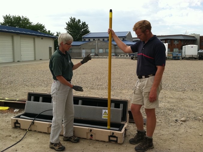
Figure 1. USGS hydrologists prepare a borehole NMR tool for logging (Source: USGS).
Recent advances in the use of NMR have resulted in the design of slimline NMR tools that fit into small, 2-inch diameter boreholes (open or cased with PVC) typically used in groundwater and environmental investigations (Walsh et al., 2013).The slimline NMR tool (Figure 1) is lighter and more portable than the tools used in the oil industry. It ranges in size from a one-person carry system to larger ones weighing 300-500 pounds. that require more than one person to set up and use.
Typical Uses
While most geophysical methods provide indirect measurements of hydrogeologic properties, NMR is unique in that it provides a direct estimate of the formation water content and pore structure (Behroozmand et al., 2014).The NMR log provides vertical distribution of water content (porosity in the saturated zone) that can be correlated to hydrostratigraphic layers. Mobile and immobile water content can be estimated from the pore-size distribution; depending on the tool used, immobile water content can be further divided into capillary- and clay-bound water. NMR can also indirectly measure the growth of biofilm in subsurface pore fluids (Zhang, et al., 2021![]() ).
).
Empirical relationships can be used to estimate the following properties (ITRC, 2019):
- Vertical distribution of water content.
- Porosity (total and effective).
- Pore-size distribution.
- Permeability.
- Hydraulic conductivity.
- Hydrocarbon content in pore fluids.
Understanding the heterogeneity of the subsurface and aquifer systems at groundwater sites is fundamental to developing a CSM that will support cleanup efforts at contaminated sites. NMR data from additional wells at a site can be correlated to identify preferential pathways for contaminant migration (e.g., more permeable layers within a formation).
The varying hydraulic conductivity of subsurface zones can be used to identify preferential flow pathways. This understanding of contaminant fate and transport informs the design of remedial systems. NMR can aid in placing well screens for water extraction wells by locating strata with higher hydraulic conductivity. The application of NMR to differentiate between water and hydrocarbons in the pore space based on the unique NMR signals from the different pore fluids is an area of active research (Coates, R.C, L. Xiao, and M. Prammer, 1999![]() ).
).
Theory of Operation
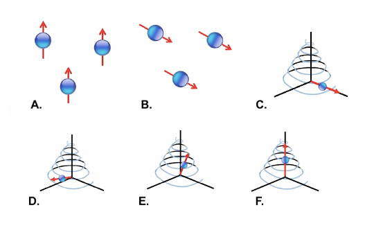
Figure 2. In an NMR measurement, (A.) water molecules align with the tool magnet, establishing a 'background state'. (B.) The molecules are pushed out of alignment with the background state by pulses of radio frequency emitted by the tool antenna. In (C.), (D.), and (E.), the molecules 'relax' back to (F.), the background state (Source: USGS).
NMR measures the spin of hydrogen protons in water molecules. NMR instruments perturb the static magnetic field using a combination of permanent magnets and radio frequency induction coils (antennae). The permanent magnets on the tool create a static "background" magnetic field, which causes the hydrogen nuclei in the water of the formation to align with the magnet. An oscillating magnetic field is created by the antennae, which transmit precisely timed bursts, or pulses, of radio-frequency energy. The energy pushes the hydrogen nuclei out of alignment with the background applied, static field. The spins of the protons return to their original state during a relaxation phase. As protons "relax," they emit a signal that is measured by the NMR tool (Dlubac et al., 2013![]() ). Figure 2 depicts the precession (or wobble of the rotational axis) of the hydrogen nuclei as they return to their original orientation.
). Figure 2 depicts the precession (or wobble of the rotational axis) of the hydrogen nuclei as they return to their original orientation.
The NMR logging tool measures both the magnetization strength and the relaxation time. The initial signal strength is directly proportional to the total amount of water present. T2 is the relaxation time associated with the decay of the magnetization in the direction perpendicular to the background applied static field (the time to go from B to E in Figure 2). Long relaxation times correspond with large pores and more mobile water, while shorter relaxation times correspond with small pores and less mobile water (ITRC, 2015).
↩System Components
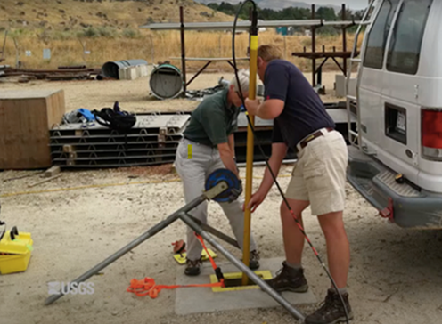
Figure 3: USGS scientists prepare to collect a nuclear magnetic resonance (NMR) log at a well (Source: USGS).
The borehole NMR tools typically used for groundwater investigations (Figure 3) consist of an NMR logging tool, tripod and pulley, cable spool and winch, laptop with inversion modeling software, a reference coil to detect background noise, and a power source. The NMR tool itself is composed of permanent magnets and radio frequency induction coils.
↩Modes of Operation
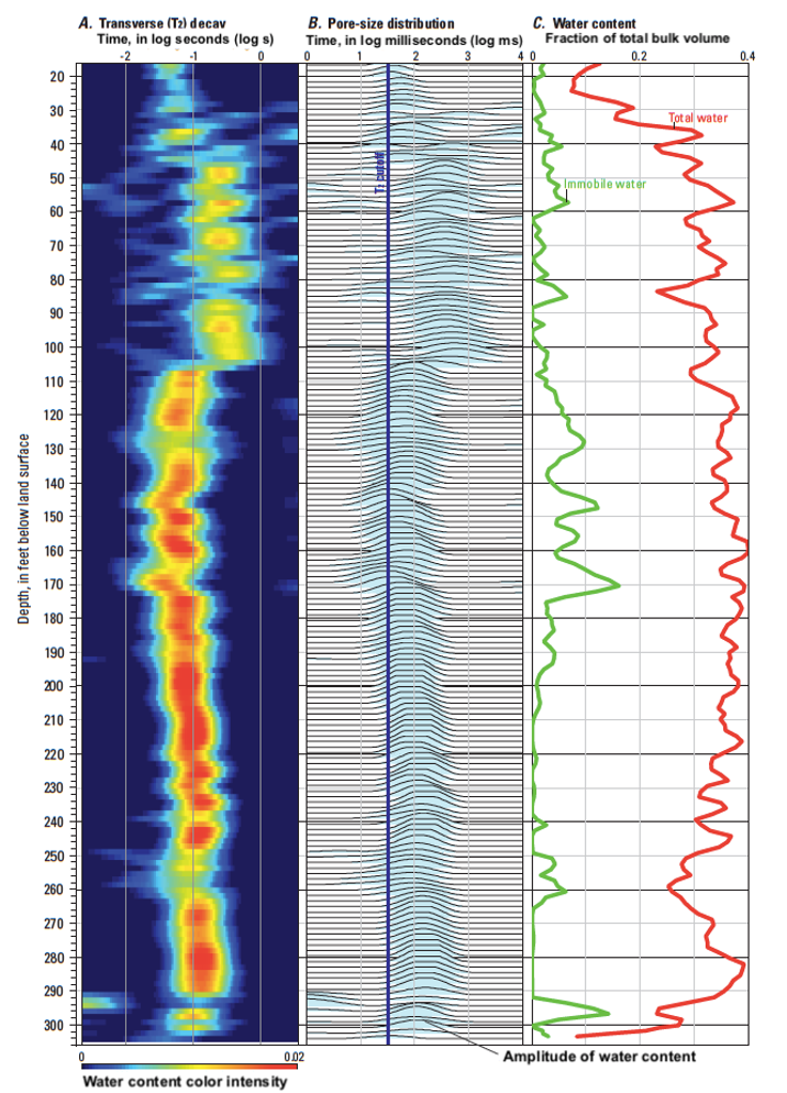
Figure 4. Nuclear magnetic resonance logs from well MA-FSW 750-0100 in East Falmouth, Massachusetts, including A. relax time, B. pore-size distribution, and C. total and immobile fractional water content. The nuclear magnetic resonance (NMR) transverse (T2) decay (A.) shows water content in color intensity as a function of relaxation time in log seconds (lower water content is shown in blue and higher water content is shown in red). The pore-size distribution (B.) shows the amplitude of water content as a function of relaxation time in log milliseconds and the T2 cutoff (33 milliseconds) as a dark blue line. All water content less than (relaxation faster than) the T2 cutoff is immobile, and water greater than (longer than) the T2 cutoff is mobile. The total water content (red) and immobile water content (green) as a fraction of the total bulk volume are shown as continuous line plots (C.) (Hull, et al., 2019).
At groundwater sites, the borehole NMR tool is deployed in either open boreholes or boreholes cased with polyvinyl chloride (PVC) pipe. Because of the strong magnets in the tool, it cannot be used in boreholes cased with steel pipe. The boreholes can be fluid-filled or dry. The tool also can be combined with direct push methods. A casing is "pushed" to the target depth, and the tool is deployed through the casing and out the bottom to collect either discrete or continuous data (ITRC, 2019).
↩Data Display and Interpretation
Borehole NMR tools generate plots of the T2 decay data, along with the pore -size distribution, total water content and fraction of immobile water, and hydraulic conductivity estimates. Capillary and clay-bound water may be determined by some tools based on the echo spacing (Te)2 of the tool. A T2 cutoff (typically 31-33 ms) is used to distinguish between mobile and immobile water content. Figure 4 shows a typical NMR plot.
↩Performance Specifications
The performance specifications for the NMR tool typically used at groundwater sites include tool diameter, radius of investigation, vertical resolution, and logging speed.
| Parameter | Typical Range |
| Tool Diameter3 | 1.75 - 5.25 inches |
| Radius of Investigation4 | 3 - 10 inches |
| Vertical Resolution5 | 0.8 - 3 feet |
| Logging Speed6 | 15 - 200 feet/hour |
Advantages
Advantages of NMR include:
- It is the only available geophysical tool that simultaneously makes measurements to estimate porosity, pore-size distribution, and hydraulic conductivity (ITRC, 2019).
- It produces quantitative data that complement more qualitative geological well logs. While estimates of total porosity can be obtained using a neutron logging tool, it requires a radioactive source, which can be problematic at some sites.
- It can differentiate between water and hydrocarbons in pore fluids, to estimate the relative saturation of each (Coates, R.C, L. Xiao, and M. Prammer, 1999
 ).
). - It provides more continuous and less costly data to estimate hydraulic conductivity than packer tests and is not limited to estimates at screened intervals.
- It can be conducted in existing PVC-cased monitoring wells, eliminating the need for additional drilling.
- It can be deployed via direct push methods (ITRC, 2019).
- It does not require that the borehole be filled with groundwater and does not require pumping or injection of water.
- Vertical depth of investigation is not limited by tool constraints. It is limited only by cable lengths.
Limitations
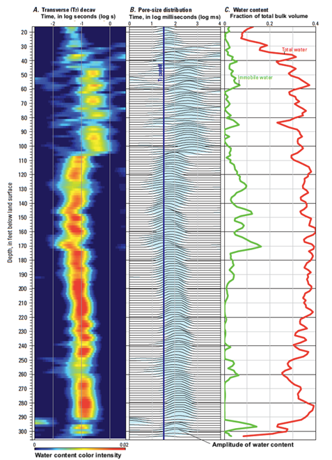
Figure 5. The sensitive shell of an NMR tool within a borehole is shown in red. The borehole is shown in white, and the disturbed zone around the borehole is dark gray (Source: USGS).
Limitations of NMR include (ITRC, 2019):
- Industrial noise from nearby power lines, electrical generators, and other sources may interfere with the NMR signal.
- NMR tools have a specific maximum "sensitive shell diameter" that is a function of the tool magnet, the radio-frequency impulse imposed to create an oscillating magnetic field, and the power output. An NMR tool must be selected with a sensitive shell diameter that is at least 2 inches greater than the original borehole or well diameter (Figure 5). Tools with an insufficient sensitive shell diameter will collect data within the disturbed material adjacent to the borehole/well casing. This reading will not reflect the true formation properties.
- Vertical resolution of the NMR tool typically ranges from 0.8 to 3 feet. Select an NMR tool based on the vertical resolution requirement of the project.
- Logging speed of NMR tools ranges from 15 to 200 ft/hr. ITRC's NMR checklist (2015) lists typical logging speeds of approximately 50 ft/hr, but they may be much slower for obtaining a log with suitable resolution.
- Well casing must be made of a non-conductive material. Note that running the tool in steel casing can damage the NMR tool.
Cost
NMR tools typically cost around $55,000-$250,000 (USD) (ITRC, 2019). A general rule of thumb for rental rates is 20-25% of the tool cost monthly, and 6-10% of the tool cost weekly. The equipment can be rented from various vendors, or geophysical service providers can be hired to perform the logging.
↩Case Studies
Investigating the Sensitivity of Emerging Geophysical Technologies to Immobile Porosity and Isolated DNAPL and Dissolved/Sorbed VOC Mass in Fractured Media
Slater., L.D., F. Day-Lewis, et al.
SERDP Project ER-2321. pp 285. 2020.
Report summarizing research to determine the sensitivity of two emerging technologies, NMR and complex resistivity to pore-size distribution and permeability. The study evaluated the potential sensitivity of the two geophysical methods to contaminant mass isolated within the immobile porosity of fractured rock. The study also evaluated the predictive capabilities of the technologies in reference to quantifying immobile porosity and contaminant mass concentration.
Surface and Borehole Nuclear Magnetic Resonance as a Characterization Tool for Managed Aquifer Recharge
Grunewald, E., and D. Walsh.
FastTimes Vol 24, pp 88-93. 2019.
Study details how NMR geophysics is being used by jurisdictions in Denver, Phoenix, and Tucson to characterize and manage their water resources.
A Field Study of Nuclear Magnetic Resonance Logging to Quantify Petroleum Contamination in Subsurface Sediments
Fay, E.L., R.J. Knight, and E.D. Grunewald.
Geophysics Vol 82, Issue 4, pp EN81-EN92. 2017.
NMR logging measurements were used to investigate an area of hydrocarbon contamination from leaking underground storage tanks (USTs) in South Dakota. Diffusion coefficient and relaxation time measurements were collected in two PVC-cased monitoring wells to detect a contaminant smear zone. The study revealed that NMR logging, under certain circumstances, can be used to detect and quantify in situ contamination, but sediment and contaminant properties at many sites may result in insufficient contrast of the diffusion coefficient and relaxation time.
NMR-Based Sensors for In Situ Monitoring of Changes in Groundwater Chemistry
Konzuk, J.
SERDP Project ER-2534. pp 105. 2017.
The report evaluated the applicability of an NMR relaxation-based sensor to identify chemical parameters associated with the natural attenuation of chlorinated ethenes. The study sought to:
Aquifer Characterization in the Indian Wells Valley, California Using Geophysical Techniques – A Pilot Study
Crews, J., A. Behroozmand, and R. Knight.
Center for Groundwater Evaluation and Management, 2016.
Report presents the results of a study to assess the potential for two different geophysical methods to augment tradition techniques in a hydrogeologic investigation in the Indian Wells Valley, California. Time-domain electromagnetics (TEM) and NMR were used in the pilot study to assess their ability to 1) delineate major coarse-grained and fine-grained geologic units, 2) identify the water table in areas without well control, and 3) identify the transition from brackish groundwater to fresh groundwater.
In Situ Detection of Subsurface Biofilm Using Low-Field NMR: A Field Study
Kirkland, C.M., P. Herrling, et al.
Environmental Science Technology. 49. pp 11045-11052. 2015.
The study showed that a small diameter NMR logging tool could detect biofilm accumulation in the subsurface using changes in T2 relaxation behavior over time.
A Small-Diameter NMR Logging Tool for Groundwater Investigations
Walsh, D., et al.
Groundwater 51, no. 6:914-026. 2013.
Paper provides the design approach taken to produce a small-diameter NMR tool for use in both open and PVC-cased boreholes and results of field testing the tool. Boreholes as small as 2 inches in diameter can be surveyed using the tool. Field results from application at several contaminated sites are included.
↩References:
Allen, D., C. Flaum, et al., 2000. Trends in NMR Logging![]() .
.
Behroozmand et al., 2015. A Review of the Principles and Applications of the NMR Technique for Near-Surface Characterization. Surveys in Geophysics. 36, 27-85.
Coates, R.C, L. Xiao, and M. Prammer, 1999. NMR Logging Principles and Applications![]() .
.
Dlubac, K., Knight, R, et al., 2013. Use of NMR Logging to Obtain Estimates of Hydraulic Conductivity in the High Plains Aquifer, Nebraska, USA![]() .
.
Hull, R.B, et al., 2019. Lithostratigraphic, Geophysical and Hydrogeologic Observations From a Boring Drilled to Bedrock in Glacial Sediments near Nantucket Sound in East Falmouth, Massachusetts. U.S. Geological Survey Scientific Investigations Report 2019-5042, 27 p.
ITRC, 2019. Advanced Site Characterization Tools (ASCT). Webpage.
ITRC, 2015. Integrated DNAPL Site Characterization and Tools Selection. Webpage.
Key, W., 1990. Borehole Geophysics Applied to Ground-water Investigations
U.S. Geological Survey, Techniques of Water-Resources Investigations, Book 2, Chapter E-2.
Kleinburg, R.L., 2001. Part 4: NMR Well Logging at Schlumberger. Concepts in Magnetic Resonance. 13(6) 396-403![]()
Rabi, I.I., Zacharias, et al., 1938. A New Method of Measuring Nuclear Magnetic Moment![]() .
.
Schlumberger, 2021. Oilfield Glossary. Website consulted June 2021.
U.S. Environmental Protection Agency (U.S. EPA), 2018. Smart Scoping for Environmental Investigations Technical Guidance![]() . 542-G-18-004, 19 p., November.
. 542-G-18-004, 19 p., November.
U.S. Environmental Protection Agency (U.S. EPA), 2011. Environmental Cleanup Best Management Practices: Effective Use of the Project Life Cycle Conceptual Site Model![]() . Office of Solid Waste and Emergency Response, 542-F-11-001, 12 p., July.
. Office of Solid Waste and Emergency Response, 542-F-11-001, 12 p., July.
U.S. Geological Survey (USGS). Borehole Nuclear Magnetic Resonance (NMR).
Walsh, D., et al, 2013. A Small-Diameter NMR Logging Tool for Groundwater Investigations.
Zhang, Y., et al., 2021. Non-Invasive Measurement, Mathematical Simulation and In Situ Detection of Biofilm Evolution in Porous Media: A Review
Applied Science, 11(4), 1391, February.
Helpful Information
-
A conceptual site model (CSM) is an iterative tool used by project teams to summarize and visualize available information on a site, as well as uncertainties associated with that information to support project and site decision-making through the entire life cycle of investigation and cleanup of a site. The CSM not only supports technical decision-making but also is a useful tool for communication and consensus-building with stakeholders (U.S. EPA 2018
; U.S. EPA 2011). ↩ -
A conceptual site model (CSM) is an iterative tool used by project teams to summarize and visualize available information on a site, as well as uncertainties associated with that information to support project and site decision-making through the entire life cycle of investigation and cleanup of a site. The CSM not only supports technical decision-making but also is a useful tool for communication and consensus-building with stakeholders (U.S. EPA 2018
; U.S. EPA 2011). ↩ Echo spacing (Te) is the time between each echo in an NMR measurement. The shorter the echo spacing,the earlier the decay that can be measured. This allows for better determination of early-time decay and water retained in the clay fraction. Te is a parameter to consider along with well dimensions and measurement of shell dimensions when selecting a tool to use. ↩
Echo spacing (Te) is the time between each echo in an NMR measurement. The shorter the echo spacing,the earlier the decay that can be measured. This allows for better determination of early-time decay and water retained in the clay fraction. Te is a parameter to consider along with well dimensions and measurement of shell dimensions when selecting a tool to use. ↩
The diameter of the NMR tools varies with the specific tool/manufacturer. In general, tools range in diameter from 1.75 inches to 5.25 inches (ITRC, 2019). Selecting the right tool for the borehole diameter is important so that the sensitivity shell of the tool falls outside of the disturbed region of the formation adjacent to the borehole/well. ↩
The diameter of the NMR tools varies with the specific tool/manufacturer. In general, tools range in diameter from 1.75 inches to 5.25 inches (ITRC, 2019). Selecting the right tool for the borehole diameter is important so that the sensitivity shell of the tool falls outside of the disturbed region of the formation adjacent to the borehole/well. ↩
Radius of investigation refers to the distance beyond the borehole/well that the tool can measure the properties of the formation. The radius of investigation is limited by the sensitivity shell of the tool. The sensitivity shell is determined by the frequency and bandwidth of the pulses emitted by the antenna. Therefore, the radius of investigation of the tool depends on the antenna (Coates, R.C, L. Xiao, and M. Prammer, 1999
). The radius of investigation (sensitivity shell) can range in diameter from 3 to 10 inches (ITRC, 2019). ↩Radius of investigation refers to the distance beyond the borehole/well that the tool can measure the properties of the formation. The radius of investigation is limited by the sensitivity shell of the tool. The sensitivity shell is determined by the frequency and bandwidth of the pulses emitted by the antenna. Therefore, the radius of investigation of the tool depends on the antenna (Coates, R.C, L. Xiao, and M. Prammer, 1999
). The radius of investigation (sensitivity shell) can range in diameter from 3 to 10 inches (ITRC, 2019). ↩Vertical resolution of the NMR tool typically ranges from 1.5 to 3 feet and depends on the tool manufacturer (ITRC, 2019). In general, the length of the antenna determines the vertical resolution, although the logging speed can also factor into determining the vertical resolution (Coates, R.C, L. Xiao, and M. Prammer, 1999
). As the tool is moved through the borehole, polarized hydrogen nuclei that are already tipped transverse to the background magnetic field are left beyond the sensitive shell, and nuclei that have not yet been tipped enter the sensitive shell. Because of this, the measured amplitude of the later spin echoes is reduced if the antenna is too short, or the logging speed is too fast. Typically, to maintain an acceptable logging speed, a 10% loss of accuracy is accepted (Coates, R.C, L. Xiao, and M. Prammer, 1999). If the tool is stationary to collect a reading, the vertical resolution will equal the antenna length. If data are collected while the tool is moving, the vertical resolution will decrease at a rate proportional to the logging speed (Coates, R.C, L. Xiao, and M. Prammer, 1999). ↩Vertical resolution of the NMR tool typically ranges from 1.5 to 3 feet and depends on the tool manufacturer (ITRC, 2019). In general, the length of the antenna determines the vertical resolution, although the logging speed can also factor into determining the vertical resolution (Coates, R.C, L. Xiao, and M. Prammer, 1999
). As the tool is moved through the borehole, polarized hydrogen nuclei that are already tipped transverse to the background magnetic field are left beyond the sensitive shell, and nuclei that have not yet been tipped enter the sensitive shell. Because of this, the measured amplitude of the later spin echoes is reduced if the antenna is too short, or the logging speed is too fast. Typically, to maintain an acceptable logging speed, a 10% loss of accuracy is accepted (Coates, R.C, L. Xiao, and M. Prammer, 1999). If the tool is stationary to collect a reading, the vertical resolution will equal the antenna length. If data are collected while the tool is moving, the vertical resolution will decrease at a rate proportional to the logging speed (Coates, R.C, L. Xiao, and M. Prammer, 1999). ↩Logging speed is related to the length of the magnet used on the specific NMR tool. As the tool moves through the borehole, it encounters "new" unpolarized hydrogen nuclei and leaves behind "old" polarized nuclei. The time it takes for the new nuclei to become fully polarized before entering the sensitivity shell of the tool is controlled by the T1 relaxation times. The length of the tool magnet and the logging speed are directly related to polarization time. The magnet must be of a sufficient length that the hydrogen nuclei are fully polarized before they enter the sensitivity shell. If the logging speed is too fast, hydrogen nuclei that are not fully polarized will be surveyed. A longer magnet allows the tool to run at a higher logging speed (Coates, R.C, L. Xiao, and M. Prammer, 1999
). Logging speeds vary with tool and manufacturer but can range from 15 to 200 ft/hr (ITRC, 2019). ↩Logging speed is related to the length of the magnet used on the specific NMR tool. As the tool moves through the borehole, it encounters "new" unpolarized hydrogen nuclei and leaves behind "old" polarized nuclei. The time it takes for the new nuclei to become fully polarized before entering the sensitivity shell of the tool is controlled by the T1 relaxation times. The length of the tool magnet and the logging speed are directly related to polarization time. The magnet must be of a sufficient length that the hydrogen nuclei are fully polarized before they enter the sensitivity shell. If the logging speed is too fast, hydrogen nuclei that are not fully polarized will be surveyed. A longer magnet allows the tool to run at a higher logging speed (Coates, R.C, L. Xiao, and M. Prammer, 1999
). Logging speeds vary with tool and manufacturer but can range from 15 to 200 ft/hr (ITRC, 2019). ↩