Groundwater Samplers
- Direct-Push Technologies
- Explosives
- Fiber Optic Chemical Sensors
- Gas Chromatography
- Geophysical Methods
- High-Resolution Site Characterization (HRSC)
- Immunoassay
- Infrared Spectroscopy
- Laser-Induced Fluorescence
- Mass Flux
- Mass Spectrometry
- Open Path Technologies
- Passive (no purge) Samplers for Groundwater
- Test Kits
- X-Ray Fluorescence
Introduction
Percussion hammer direct-push system. Courtesy of Geoprope Systems.
Groundwater sampling with direct-push systems (DPS) has gained widespread acceptance in the environmental industry over the past decade because of the versatility, relatively low cost, and mobility of these systems. The two major classes of direct-push platforms are cone penetrometer testing (CPT) and percussion hammer systems. The distinction between these systems is that CPT advances the tool string by applying a hydraulic ram against the weight or mass of the vehicle alone, while percussion hammer units use a hammer to drive the tool string into the ground. These systems share the same principle of operation, similar tools, and a number of advantages and limitations. Some percussion hammer rigs also add a high-frequency vibration feature to driving the probe into the ground.
The relatively low cost of taking groundwater samples with DPS allows the collection of a larger number of samples both horizontally and vertically than could be done using conventional rigs. This density of sample taking provides a better idea of where source zones are and contaminant plume architecture which maximizes permanent monitoring well placement efficiency and the design of the remedy.

Twenty-five ton CPT Rig. Courtesy of Precision Sampling.
Typical Uses
Hand truck percussion hammer rig.
Courtesy of Precision Sampling.
Direct-push systems provide advantages when collecting groundwater samples. In particular, direct-push systems are quicker and more mobile than traditional drill rigs. Sampling and some data collection are faster, reducing the time needed to complete an investigation and increasing the number of points that can be sampled during the investigation. Shorter screen lengths allow sampling of precise depth intervals, which is especially important when sampling a contaminant plume from a source with a complex architecture such as may be found with dense nonaqueous phase liquids (DNAPL).
In spite of these advantages, there are some limitations of groundwater sampling using direct-push systems. Because direct-push sampling tools are not developed like conventional monitoring wells, samples may be turbid. Turbidity is a particular concern when the target analytes are metals or organic compounds with a tendency to be sorbed onto the surfaces of clays silts, or naturally occurring organic compounds such as humic acids. When sampling for these analytes, investigators should consider using small wells installed using direct-push tools. These wells can be developed like conventional monitoring wells and provide comparable quality samples. There are samplers, such as the BAT system (see below), that use ceramic or other porous tips to draw water through that will provide a low-turbidity sample.
Direct push groundwater sampling tools/techniques generally can be grouped into these categories: passive samplers, sealed-screen samplers, exposed-screen samplers, and open-hole sampling.
Passive Samplers
The high-resolution passive profiler (HRPP) is a passive sampler designed to quantify and delineate concentrations of chlorinated volatile organic compounds (CVOCs), geochemical indicators, and CVOC-degrading microorganisms/genes using a single co-located depth profile in a saturated environment. HRPP can also perform compound-specific stable isotope analysis (CSIA) of CVOCs and estimate groundwater velocity at less than 30 cm vertical resolution. It can be used to measure a wide range of contaminants such as metals, anions, and volatile organic compounds (VOCs), and can be adapted with solid-phase microextraction (SPME) fibers to measure hydrophobic organic compounds (HOCs), including PAHs, PCBs, and DDX.
The device is made of stainless steel or polycarbonate and is advanced via direct-push methods or by hand to a target depth in unconsolidated sediments (e.g., shallow aquifer, marine, or freshwater sediments). The maximum depth of deployment is about 9 meters. It is typically left in place for three weeks prior to retrieval and analysis.
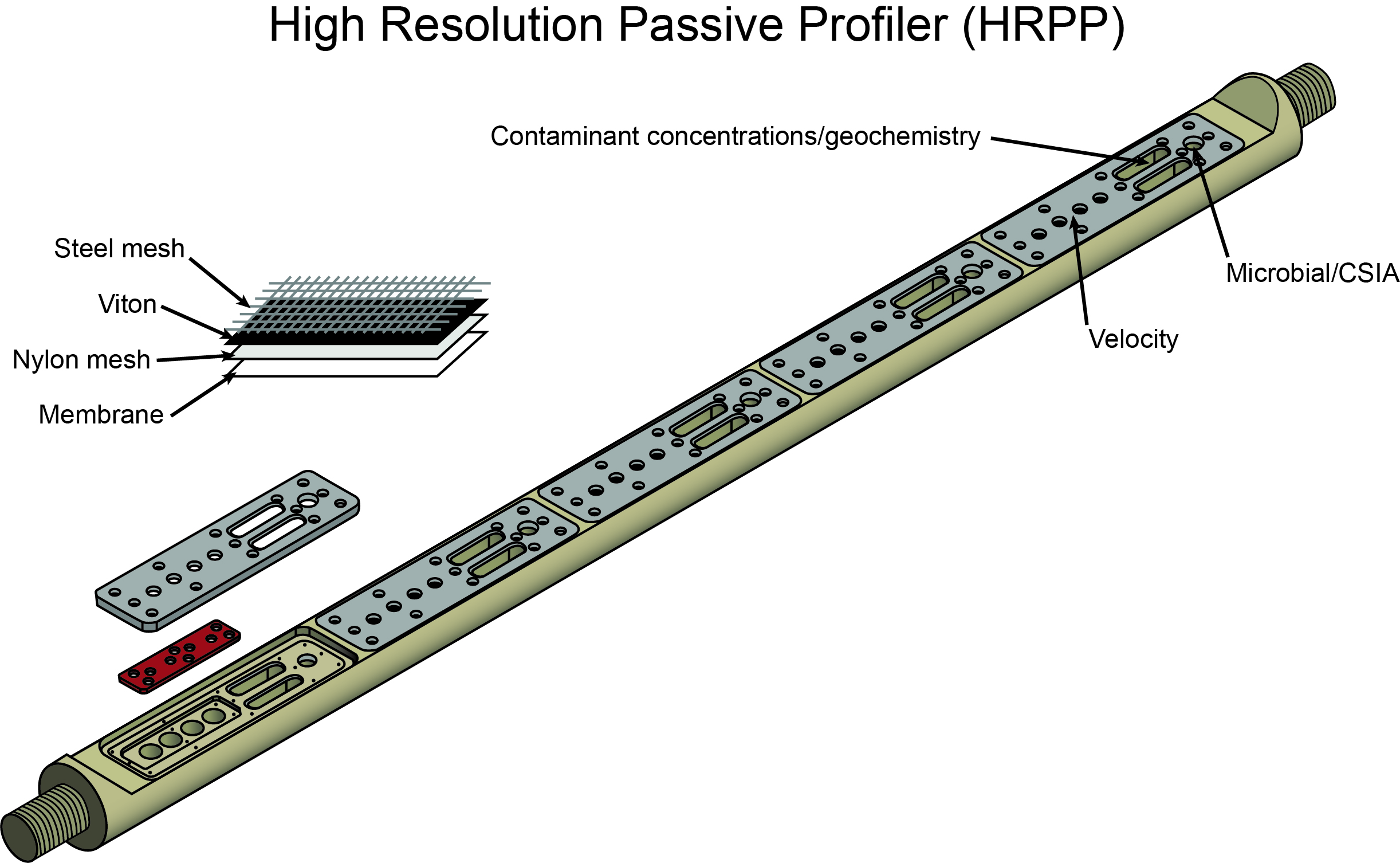
Courtesy of H.Schneider, W.A. Jackson PhD., P.B. Hatzinger PhD., and C.E. Schaefer PhD.
Equilibrium cells on the HRPP function to quantify contaminant concentrations and geochemical conditions through the diffusion of contaminants and geochemical indicators across a membrane over the three-week deployment.
HRPP can be used to assess the distribution, fate, and availability of contaminants; evaluate the performance of remediation or natural attenuation, including corresponding reductions in long-term risk; and increase the understanding of the fate and transport of chemicals of concern and the impact of treatment on sediment geochemistry, microbial processing, and sediment pore water transport.
Sealed-Screen Samplers
Sealed-screen samplers typically consist of a short screen contained within a sealed, water-tight body. To collect the sample, the tool is driven to the desired depth where the protective outer rod is withdrawn exposing the screen to groundwater. The water flows through the screen and into the drive rods or sample chamber. O-ring seals placed between the drive tip and the tool body help ensure that the sampler is water tight as it is driven to the target depth. The integrity of the seal can be checked by lowering an electronic water level indicator into the sampler prior to withdrawing the outer rod. Because the tool is sealed, the potential for cross contamination is greatly reduced and a true depth-specific sample can be collected. The sample volume collected with some sealed screen samplers is limited by the volume of the sample chamber.
These types of samplers can only sample one interval per push. If the sampler uses the walls of the rod for containing the groundwater until it can be retrieved by bailer or pump, care should be taken to ensure that the target contaminants are not sensitive to interaction with iron (e.g., dissolved oxygen, redox potential, and trace metals).
Exposed-Screen Samplers
Waterloo Profiler® Courtesy Precision Sampling, Inc.
Exposed-screen samplers are capable of collecting groundwater samples at multiple intervals as the sampling tool is advanced, without having to withdraw the tool for sample collection or decontamination. The terminal end of a typical exposed-screen sampler has a 6-inch- to 3-foot-long screen made up of fine-mesh, narrow slots, or small holes. The screen remains open to formation materials and water while the tool is advanced. This allows samples to be collected either continuously or periodically as the tool is advanced to vertically profile groundwater chemistry and aqueous-phase contaminant distribution.
Exposed-screen samplers can be used to measure water levels at discrete intervals within moderate- to high-yield formations to assist in defining vertical head distribution and gradient. Additionally, some of these tools can be used to conduct hydraulic tests at specific intervals to characterize the hydraulic conductivity of formations to identify possible preferential flow pathways and barriers to flow.
The Waterloo Profiler® minimizes the potential for cross contamination. It uses a 6-inch-long, uniform diameter, stainless-steel sampling tool into which several inlets or sampling ports have been drilled and covered with fine-mesh screen. As the tool is advanced, distilled or deionized organic-free water is slowly pumped down tubing that runs inside the drive rod and leads to the sampling ports in the tool. The water keeps groundwater from entering the tool while it is advanced. A peristaltic pump is typically used for water head depths less than 25 feet. A double-valve pump can be used for sampling at greater depths.
After the first target interval is reached, the flow of the pump is reversed and the sampling tube is purged so water representative of the aquifer is obtained. After the sample is collected, the pump is reversed and distilled or deionized organic-free water is again pumped through the sampling ports. The tool is then advanced to the next target interval where the process is repeated.

Waterloo Advanced Profiling System™ Courtesy Stone Environmental, Inc.
The Waterloo Advanced Profiling System (WaterlooAPS™) allows physiochemical data acquisition. The stainless-steel profiling tip has 16 ports arranged in four rows, resulting in an open sampling interval approximately 2.5 inches in length. Each of the rows is recessed and fitted with dual filter screens. The mesh size of the inner screen can be changed to reduce turbidity or optimize sampling productivity. To minimize sorption of contaminants to system materials, stainless steel tubing convey groundwater from the profiling tip to the sample collection apparatus at the surface. A sacrificial profiling tip allows retraction grouting of completed profiling boreholes. Groundwater samples are collected at discrete depth intervals using either a peristaltic or downhole nitrogen gas-drive pump, depending on depth to the water table. Samples are collected directly into glass, zero-headspace, in-line sample containers that prevent sample contact with system materials and ambient air. The containers are located on the suction side of the peristaltic pump to prevent contact with pump head tubing during use of that sampling method.
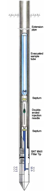
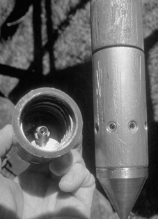
BAT® Sampler. Courtesy BAT Geosystems, AB
The BAT® system consists of a tip, screen, and housing with sampling chamber. The top of the chamber is sealed with a disc containing a flexible septum. The tip is constructed of high-strength thermoplastic or stainless steel. The screen, which is either ceramic or porous polyethylene, allows water to enter the sampling chamber when put under vacuum. To take a sample, the tool is driven to the desired sampling depth. A sample holder containing an evacuated sample vial (35 to 500 mL) with a septum cap and a double-ended hypodermic needle is then lowered down the push rod. When the vial encounters the top of the sample chamber, the needle penetrates the chamber septum at the same time it penetrates the vial septum, allowing water to enter the vial. When the vial is full, it is retrieved and stored for subsequent analysis. The procedure is repeated until sufficient water is collected to meet analytical needs. The tool can then be driven to another depth and sampled or withdrawn, cleaned, and driven in a different location.
Open-hole sampling is conducted by advancing drive rods with a drive point to the desired sampling depth. Upon reaching the sampling depth, the rods are withdrawn slightly which separates them from the drive tip and allows water to enter. The water can be sampled by lowering a bailer into the rods or by pumping. The open-hole method is only feasible within formations that are fairly cohesive, otherwise the formation soil may flow upwards into the rods when they are withdrawn, preventing water samples from being collected. With single-rod systems, open-hole sampling can only be conducted at one depth within a borehole because the borehole cannot be flushed out between sampling intervals and cross-contamination may occur.
Dual-tube systems provide continuous soil sampling capabilities. The cores can be examined and chemically screened as they are taken, and decisions made as to whether a groundwater sample should be taken at that level. Because the dual tube has an outside casing that is driven with the drive point, it minimizes drag down potential and allows multiple-level sampling within the outer casing. The water that is in the casing between sampling points will need to be purged to ensure a representative sample. Many vendors that offer sealed sampling tools prefer to use dual-tube systems to advance the rods to the desired point of sampling and either lower the screen to the bottom of the hole and withdraw the outer casing allowing fresh water in, or drive the sampler to a point slightly ahead of the rods. By lowering the tool to the bottom of the already driven hole or driving it a short distance into the ground ahead of the rods, the life of the tool is extended and excellent stratigraphical information is obtained from the cores.
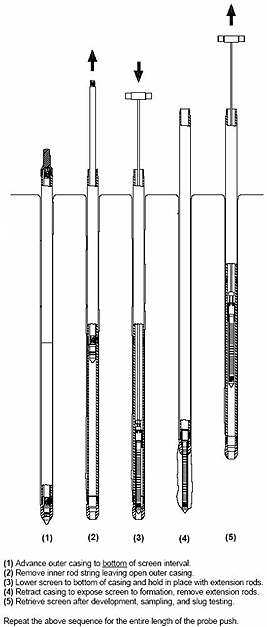
Dual-Tube Groundwater Profiler. Courtesy of Geoprobe Systems®
Monitoring Wells and Piezometers
Direct-push systems can also be used to install temporary or permanent monitoring wells and piezometer. These wells can be installed in several ways. The first and most direct is to drive a well point to the depth to be sampled. Well points are generally constructed of slotted steel pipe or continuous-wrap, wire-wound, steel screens with a tapered tip. If the well point will be left in the ground for any length of time, a seal to prevent infiltration of surface water will be needed.
A second method of well installation is to drive a rod casing with an expendable tip to the depth to be monitored. The well string is placed in the casing with the screen resting on the expendable tip. Depending upon the inside diameter of the drive casing and the outside diameter of the well casing, it may not be possible to set a sand filter around the screen. If a sand pack is not possible, the outer casing is withdrawn and the formation is allowed to collapse around the screen and well casing. This technique will probably not yield low turbidity samples in formations that are rich in fines. If a dual-tube rig is used, a continuous soil core can be taken that will aid in selecting monitoring depths.
The third technique is similar except that it uses well screens with prepacked filters. Direct push wells completed in this fashion are comparable to conventional wells. A modular sleeve with fine sand or bentonite can be placed above the filter to prevent infiltration of grout or other material used for sealing the annular space.
Direct-push monitoring well. Courtesy of Geoprobe Systems®
Multiport collectors are another technological advance that expands the single-use functionality and increases the understanding of aquifer characteristics. In one system, a multiport sleeve and a deflated membrane are placed using a hollow rod. Holding the assemblage in place, the rod is retracted, and the membrane is inflated, usually with water. This pushes the multilevel sampler to the side of the borehole. Small diameter screens with blank casing are pushed down into the sleeve. Perforations in the sleeve allow groundwater to enter the screens. Generally up to three depths can be sampled from a single borehole. The whole assemblage can be removed by taking the miniwells out of the sleeves and deflating the membrane, or it can be left downhole to function as a multiport monitoring well.
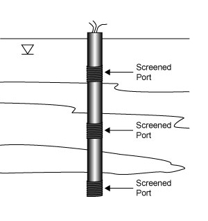
Multilevel sampler.
Multiport sampler. Courtesy of Flexible Liner Underground Technologies.
Another type of multiport sampler uses blank PVC casing as a support and places stainless steel screened ports that are connected to the surface with tubing at depths of interest. The 2-inch casing with ports is lowered into the outer drive rod casing to the bottom of the hole. As the casing is pulled, the soil is allowed to naturally collapse around the string. Depending upon the configuration, the system can measure up to 15 different zones.
Sample Collection Devices

Mechanical bladder pump. Courtesy of Geoprobe Systems®
In the simplest sampling tools (e.g., open hole), groundwater can be collected as it would be from a conventionally-installed well. Miniaturized water level indicators and small-diameter bailers are available for most direct push wells.
Another commonly-used sample collector is an inertial pump. Inertial lift pumps consist of a discharge line (either flexible tubing or rigid pipe) with a ball-check foot valve attached to its lower end. In operation, the tube is lowered into a water column and moved through an up and down motion, to achieve discharge of water. As the pump is moved upward, water that has entered the pump under hydrostatic pressure is lifted upward, held in the pump by the seated foot valve. When the upward motion of the pump is stopped, the inertia of the water column inside the pump carries it up and out of the discharge line. As the pump is pushed downward, the foot valve opens, allowing the pump to refill. If inertial-lift pumps are cycled rapidly prior to or during sample collection, some loss of VOCs and/or dissolved gases could occur in the discharge stream as well as increasing sample turbidity (EPA 2004).
Within the constraints of well depth and diameter, a wide variety of pumps can be used to collect groundwater samples. Pumps are available with diameters as small as 3/8 inch for use with direct-push installed wells. Examples of pump types include bladder, mechanical bladder, and double valve. Some of these pumps have additional features for use with mini-wells, such as rounded ends so that they can be positioned more easily in small diameter wells without hanging up.
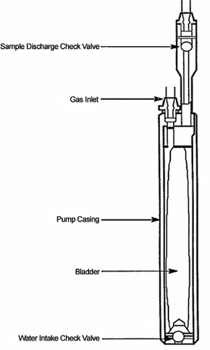
Bladder Pump. After EPA 1993.
Advantages
Field analysis and direct-push systems are often used to speed collection and reduce costs on projects where the sites are large, a high volume of data points are needed, the sites are partly or totally inaccessible by a large drill rig, or to minimize sampling disturbances in sensitive habitats.(See https://triadcentral.clu-in.org for examples).
Groundwater sampling using direct-push technologies provides many advantages over sampling using conventionally-installed wells. Direct-push systems are quicker and more mobile than traditional drill rigs. Small percussion hammer rigs can even be used to sample inside buildings. The smaller footprint of many of the direct-push rigs also minimizes surface and subsurface disturbance. Sampling and data collection are faster, reducing the time needed to complete an investigation and increasing the number of sample points that can be collected during the investigation.
Direct-push technologies are particularly well suited for application of the Triad Approach to site investigations for sites with shallow subsurface contamination in unconsolidated soils and sediments. The Triad Approach makes use of on-site analytical tools, in conjunction with systematic planning and dynamic work plans, to streamline sampling, analysis, and data management conducted during site assessment, characterization, and cleanup.
Limitations
Groundwater sampling using direct-push systems has limitations that are important to keep in mind when considering its use for site characterization. Direct-push technologies cannot be used to collect samples from consolidated aquifers, and, in general, are limited to depths of less than 100 feet. Because some of the tools lack filters or have filters that are less effective than those of completed monitoring wells, samples may be turbid. Turbidity can usually be reduced by using wells with prepacked filters, selecting sampling tools with more complete filtration systems, or using low-flow sampling techniques. The smaller sampling interval, an advantage in some cases, can be a limitation when the goal of the investigation is depth-averaged trend analysis. Also, the smaller-diameter sampling chambers available for some sampling tools can sometimes lead to smaller available sample volumes.
Cost Data
Studies indicate that direct-push analytical systems may provide significant savings over conventional site assessment and characterization methods. Cost information varies greatly among the different technologies, as well as for projects of different scope and geologic conditions. The sites listed below provide information about the costs associated with a variety of technologies.
Resources
EPA. 2005. Groundwater Sampling and Monitoring with Direct Push Technologies, EPA 540/R-04/005. Office of Solid Waste and Emergency Response, 78 pp. http://www.clu-in.org/download/char/540r04005.pdf
EPA. 1993. Subsurface Characterization and Monitoring Techniques: A Desk Reference Guide, Volume I: Solids and Ground Water Appendices A and B, EPA 625/R-93/003a. Office of Research and Development, 498 pp. http://nepis.epa.gov/Exe/ZyPURL.cgi?Dockey=30004L8E.txt
Puls, R. and M. Barcelona. 1996. Ground Water Issue: Low-Flow (Minimal Drawdown) Ground-Water Sampling Procedures, EPA/540/S-95/504. U.S. Environmental Protection Agency, 12 pp. http://nepis.epa.gov/Exe/ZyPURL.cgi?Dockey=2000G23N.txt
Schneider, Haley A., Ph.D., W. Andrew Jackson Ph.D., Paul B. Hatzinger Ph.D., and Charles E. Schaefer Ph.D, 2020. High-Resolution Characterization of a Chlorinated Solvent Impacted Aquifer Using a Passive Profiler, 27 pp.
SERDP and ESTCP webpage, accessed February 26, 2024. High-Resolution Passive Profiling to Monitor Contaminated Sediments in Support of Remediation Evaluation and Risk Characterization, ER-201734. https://serdp-estcp.mil/projects/details/f773f67f-194d-4f73-b7a5-7a794ef1ea45/er-201734-project-overview
