Membrane Interface Probe (MIP)
- Direct-Push Technologies
- Explosives
- Fiber Optic Chemical Sensors
- Gas Chromatography
- Geophysical Methods
- High-Resolution Site Characterization (HRSC)
- Immunoassay
- Infrared Spectroscopy
- Laser-Induced Fluorescence
- Mass Flux
- Mass Spectrometry
- Open Path Technologies
- Passive (no purge) Samplers for Groundwater
- Test Kits
- X-Ray Fluorescence
Description
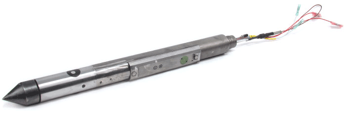
Figure 1. Membrane Interface Probe
Courtesy: Geoprobe, Inc.
Typical Uses
MIP technology is capable of sampling VOCs and some semi-VOCs from subsurface soil in the vadose and saturated zones. It is typically used to characterize hydrocarbon or solvent contamination. Its ability to rapidly locate and identify contaminants reduces uncertainty in management decisions associated with costly cleanup projects, such as those commonly involving source zones of dense non-aqueous phase liquid (DNAPL) and light non-aqueous phase liquid (LNAPL). EPA has developed a dynamic field process in which MIPs may be used to produce reliable estimates of the contaminated mass, which is crucial to achieving cost-effective cleanups. Additional information on the use of the dynamic field process is in Using Dynamic Field Activities for On-Site Decision Making: A Guide for Project Managers.
Theory of Operation
MIP technology uses heat to volatilize and mobilize contaminants for sampling. Heating the soil and/or groundwater adjacent to the MIP's semi-permeable membrane, volatilizes the VOCs, which then pass through the probe's membrane and into a carrier gas for transportation to the ground surface.
System Components
The MIP is mounted on a DPP, which drives the probe into the soil and estimates the probe's depth.
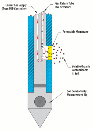
Figure 2. MIP with Soil Conductivity Tip
Courtesy Geoprobe Inc.
The MIP consists of a small polymer (tetrafluoroethene) port, or membrane, that is permeable to gas but impermeable to liquid. The port is secured onto a steel block that also contains a resistive heater coil and a thermocouple, allowing the temperature of the membrane to be controlled and monitored. The heater coil heats the soil near the membrane to 100 to 120° C (160 to 232° F), which allows VOCs in the soil and groundwater to partition across the membrane in saturated or unsaturated soil. The subsurface temperature needs to be at or above the boiling point of the target compound(s). Nitrogen is the most commonly used carrier gas, but helium has been used in some applications. The carrier gas (35-45 mL/min) sweeps across the back of the membrane, entrains the VOC sample, and carries the VOC to the detection device located at the surface.
Typically, the MIP probe includes a tip that measures soil or water conductivity at a known distance below the membrane. The conductivity measurements can help correlate contamination to known soil stratigraphy. The probe conductivity measurements cannot identify the specific type of soil (based on grain size) distribution that is encountered unless the conductivity measurements can be compared to actual site soil core data. In the absence of onsite data, the MIP conductivity measurements identify changes in the soil's electrical behavior that can be related to changes in stratigraphy or groundwater quality. Analytical devices commonly used with a MIP include gas chromatography (GC)-grade detectors (e.g., photo-ionization (PID), flame ionization (FID), electron capture (ECD), and dry electrolytic conductivity (DELCD), and halogen specific (XSD)) that establish the presence of VOC vapor, dissolved phase LNAPL, or DNAPL in soil. These detectors may be deployed singly or in line depending upon the site's contamination. PID detectors are best used for detecting aromatic compounds, such as BTEX (benzene, toluene, ethylbenzene, and xylene isomers). FID detectors are used to detect petroleum hydrocarbons (straight and branched chain alkanes). ECD, DELCD, and XSD detectors are used to identify chlorinated hydrocarbons (e.g., perchloroethene, trichloroethene, dichloroethene, carbon tetrachloride).
A hydraulic profiling tool (HPT) can also be added to the probe (Figure 3). The HPT is advanced into unconsolidated soils and sediments to assess formation permeability and hydrostratigraphy at the centimeter scale. During advancement, water is injected at a controlled rate into the formation through a screened port on the side of the HPT probe. A transducer in the probe measures the total pressure required to inject the water into the formation while a flow controller at the surface monitors the injection flow rate. These data can be used to estimate hydraulic conductivity (K) in the formation at small scale (McCall 2011).
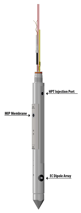
Figure 3. MIP with EC and HPT Tools
Courtesy Geoprobe Inc.
Speciation of contaminants can be accomplished either by collecting the off-gas on carbon or Tenax traps and subsequently desorbing the contaminants into a GC/mass spectrometer (MS) or by direct injection into an onsite ion-trap mass spectrometer (ITMS). Since the ITMS lacks a GC, its ability to resolve complex mixtures of contaminants is limited.
Mode of Operation
All necessary point-installation permits for digging, coring, drilling, and groundwater monitoring should be obtained prior to mobilizing equipment to the field. Prior to initiating any intrusive subsurface activities, the proposed sampling locations should be cleared and all utility lines in the investigation area should be marked. Care should be taken not to cross-contaminate deeper aquifers by puncturing an aquitard underlying the contaminated groundwater or DNAPL source.
The MIP is pushed into the ground at a rate of about a foot per minute. The push strategy depends upon the data quality objectives, soil matrix, and the chemical species that are expected to be present. For example, benzene in a sand might allow continuous sampling, while a less volatile compound in a clay matrix may require a push and hold strategy that provides more thorough heat transfer to the soil matrix. The manufacturer of the probe recommends a push and hold strategy. The time it takes for the carrier gas to transport the sample to the surface varies with the length of the carrier tubing. The detector and carrier tubing can become saturated when driving the probe through an LNAPL or DNAPL. While the carrier tubing usually can be cleared by continuous carrier-gas purging, in some instances, the probe has to be pulled and the tubing replaced.
The carrier gas can be injected directly into a measuring device. Some contractors offer logs from three detectors, including PID, ECD or XSD, and FID, as part of their normal DPP/MIP service. When a greater degree of speciation is required, an ITMS, GC, or GC/MS may be used, as discussed above.
At the conclusion of subsurface investigations, each sampling location that is not used to install a groundwater monitoring point or well should be properly sealed with bentonite chips or pellets, grout, or other appropriate material to eliminate any potential for contaminant migration to the groundwater.
For details on mode of operation, including QC procedures, see MIP SOP (disclaimer policy).
Target Analytes
Target analytes typically sampled with MIP technology include VOCs, such as BTEX and halogenated hydrocarbons. Some semi-VOCs also can be sampled.
Performance Specifications
DPP/CPT rigs are generally capable of surveying 75 m (250 ft) or more of subsurface per day and hence are far cheaper to use than obtaining similar stratigraphic information and samples for laboratory analysis with a conventional drill rig. Because the MIP is usually advanced at a rate that allows the soil matrix to be heated, a more modest 37 to 62 meters (120 to 200 feet) per day is typical. It generally takes about 75 seconds for the carrier gas (nitrogen) to travel through 200 feet of inert tubing to reach the detectors. About 20 samples per day can be analyzed when GC/MS is used as the analytic device.
Detection Limits
The MIP's detection limits depend on the soil type, temperature, and detector used. Table 1 presents a range of common detection limits for each detector.
| Table 1. Common Detection Limits of MIP Detectors | |||
|---|---|---|---|
| Detector | Contaminants | Detection Range1 (ppm) | Gases |
| PID | Hydrocarbons and Chlorinated VOCs with ionization Potential <eV of bulb | 0.20-2.0 | Carrier |
| FID | Hydrocarbons and Chlorinated VOCs | 10-20x | Carrier, Hydrogen, Air |
| ECD | Chlorinated VOCs | 0.20-2.0 | Carrier |
| DELCD | Chlorinated VOCs | 0.20-2.0 | Carrier, Air |
| XSD | Chlorinated VOCs | 0.10-2.0 | Carrier, Air |
| 1 Limiting factors include signal to noise ratio, length of trunkline, and membrane wear. Detection levels will vary with each setup due to the level of detector maintenance performed and specific detector configuration and optimization. Current detection limits must be obtained from proposed MIP operator prior to mobbing to the site.
Source: Adapted from Geoprobe |
|||
Calibration
The MIP is calibrated by inserting the probe into a sand or water standard prepared in advance with known concentrations of the VOCs of concern. For information on preparing calibration standards see MIP SOP (disclaimer policy).
Sample Preparation
While no sample preparation is needed, when MIP is deployed from a DPP, hard surfaces, such as concrete or caliche, may require drilling or cutting prior to advancing the probe into the ground.
Quality Control (QC)
Several types of quality control checks can be applied to assess whether the MIP systems are functioning properly and are producing accurate data that will be useful for project decision-making. One of the most important steps is calibration with clean sand-blank measurements taken pre- and post-push as part of the standard data collection procedure. This step ensures there is no carry-over from the previous push.
To ensure that the membrane itself is functioning correctly the manufacturer's SOP states: "A probe membrane is considered in good working condition as long as two requirements are met: 1) The butane sanity test result is greater than 1.0E+06 uV response, 2) Flow of the system has not varied more than 3 mL/min from the original flow of the system (a flow meter or bubble flow meter should be kept with the system at all times). If either one of these requirements are not met, a new face must be installed."
A qualitative assessment may be conducted by comparing subsurface contaminant cross sections generated from MIP data to borehole logs or cross sections prepared using dual tube direct push soil sampling techniques coupled with onsite GC or GC/MS confirmation data.
Precision and Accuracy
Precision refers to the reproducibility of measurements of the same characteristic, usually under a given set of conditions. Accuracy refers to the degree of agreement of a measurement to the "true" value, as determined by traditional analytical methods. Both provide a measure of the MIP system's performance and can help determine how useful the data are.
Precision is usually assessed by comparing the results of duplicate analyses. However, because MIP samples are taken in situ, it is not possible to obtain true duplicate samples. Instead, an estimate of the instrumental precision can be obtained for the entire system by evaluating the results from multiple measurements of their respective calibration check samples, which are analyzed before and after each push.
Because MIP analytical detection systems do not provide fully quantitative results, accuracy is assessed qualitatively by measuring the agreement between detect and non-detect determinations made by the MIP and by corresponding confirmatory laboratory samples. Interpretation of MIP data produced by total detectors is best done by comparing relative responses rather than absolute values.
Limitations
MIPs provide screening level data that need to be supplemented with analytical soil or groundwater data to fully support human health risk assessments or remediation decisions. Determining the depth at which the sample was taken when the sampler is in a near-continuous operating mode and the push rate is variable can be difficult. Compounds may be found in the subsurface for which the detectors were not calibrated. As with all direct push devices, MIP is only useful for deployment in unconsolidated matrices. Speciation with the ion trap mass spectrometer (ITMS) can be problematic when the gas stream contains a complex mixture of chemicals. In many cases, the detection limit of MIP equipment for specific contaminants is above the detection limit required for human health risk assessment. ITMS-MIP overestimates contaminant concentrations for most vadose zone soils when compared with validation results, and it underestimates contaminant concentrations for clay type vadose zone soils (Myers 2002).
Cost Data
The major costs of operating a MIP system involve the direct push platform and labor, MIP operating system, and detectors. Depending upon the equipment used, the cost of a MIP system with crew can range from $3,000 to $5,000 per day. If speciation of contaminants (e.g., MTBE vs. benzene or PCE vs. TCE) in the off-gasses from the MIP detector is required, a mobile lab with portable GC or GC/MS can be brought to the site. A GC can typically process 30 to 40 samples per day. Typically, speciation adds an additional $2,000 to $3,000 per day to the cost. Speciation also can be accomplished by collecting the off-gasses on carbon traps for analysis at an off-site lab. The cost per carbon trap collection for off-site analysis is about $175.
References
Accelerated VOC Source Investigation Pairing SCAPS/MIP with EPA Triad, Marine Corps Base Camp Pendleton
Collins, K.
Conference on Accelerating Site Closeout, Improving Performance, and Reducing Costs Through Optimization, San Diego, California, 42 pp, (ppt)
Application of the Geoprobe® HPT Logging System For Geo-Environmental Investigations
McCall, Wes
Geoprobe® Technical Bulletin No. MK3184, 36 pp, 2011
Defining TCE Plume Source Areas Using the Membrane Interface Probe (MIP) abstract
McAndrews, B.; K. Heinze, and W.DiGuiseppi
Soil and Sediment Contamination (formerly Journal of Soil Contamination), Volume 12, Number 6, November-December 2003, pp. 799-813
![]() Sensor Technologies Used During Site Remediation Activities:
Selected Experiences
Sensor Technologies Used During Site Remediation Activities:
Selected Experiences
U.S. EPA, EPA 542-R-05-007, 110 pp, 2005
![]() Site Characterization Technologies for DNAPL Investigations
Site Characterization Technologies for DNAPL Investigations
U.S. EPA, EPA 542/R-04/017, 165 pp, 2004
![]() Tri-Service Site Characterization and Analysis Penetrometer System Validation of the Membrane Interface Probe
Tri-Service Site Characterization and Analysis Penetrometer System Validation of the Membrane Interface Probe
Myers, K., W. Davis, and J. Costanza.
U.S. Army Corps of Engineers, ERDC/EL TR-02-16, 62 pp, 2002
Utilizing the Membrane Interface Probe (MIP)
Linn, William.
State Coalition for Remediation of Drycleaners, 2012 Conference, 28 slides.
![]() Vapor Intrusion and Ambient Air Study Final Results Report Armen Cleaners Ann Arbor, Michigan
Vapor Intrusion and Ambient Air Study Final Results Report Armen Cleaners Ann Arbor, Michigan
U.S. EPA, 139 pp, 2006
