Explosives
- Direct-Push Technologies
- Explosives
- Fiber Optic Chemical Sensors
- Gas Chromatography
- Geophysical Methods
- High-Resolution Site Characterization (HRSC)
- Immunoassay
- Infrared Spectroscopy
- Laser-Induced Fluorescence
- Mass Flux
- Mass Spectrometry
- Open Path Technologies
- Passive (no purge) Samplers for Groundwater
- Test Kits
- X-Ray Fluorescence
Overview of Environmental Issues Associated with Residues of Energetic Materials
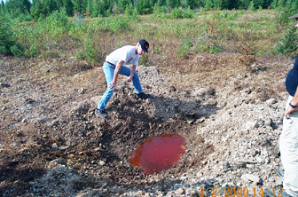
It has been estimated that there are thousands of explosives-contaminated sites within the United States, and even a greater number in Europe and the Soviet Union (Major et al., 1997). The sources of this contamination are wastes produced from synthesis of explosive chemicals; load, assemble, and pack operations of finished munitions; residues deposited during munitions testing and training; residues from ordnance demilitarization; and disposal of out-of-date and off-specification material (Yinon, 1999; Jenkins and Walsh, 1987; Major et al., 1991; Cragin et al., 1985; Selim and Iskandar, 1994; Fellows et al., 1992; EPA Handbook # EPA/625/R-93/013, 1993). These activities have led to soil contamination at ammunition plants, depots, and testing and training ranges (Figure 1-1). Contaminated soils have, in some cases, been the source of groundwater contamination in aquifers beneath these facilities. Nevertheless, the need to maintain our military in a state of combat readiness requires that production, testing, and training with energetic materials continues.
| Figure 1.1. Pink water in crater formed by the dissolution of TNT from a 500-lb. bomb that partially detonated (low-ordered). Note the large pieces of casing on the backside of the crater. The concentration of TNT in the water was determined to be 19 mg/L. |
 |
The task of identifying the extent of contamination at these facilities becomes complicated when the contaminants are energetic materials. Energetic materials behave differently than most other organic contaminants and pose an immediate safety hazard when present in large quantities or within unexploded ordnance (UXO). Energetic materials include chemicals that are used by the military as propellants, explosives, and pyrotechnics (PEP). By far, the energetic compounds produced and used for the Department of Defense (DoD) in the greatest quantities are secondary explosives. To assess the extent of explosive contamination, it is necessary to detect and identify explosives and their degradation products in soil and groundwater. This module presents information on the various technologies available to assist in this characterization.
Explosives are classified as “primary” or “secondary” based on their susceptibility to initiation. Primary explosives, which include lead azide, lead styphnate, and mercury fulminate, are highly susceptible to ignition (easily detonated by heat, spark, impact or friction) and are often referred to as initiating explosives, because they can be used to initiate the detonation of secondary explosives. Secondary explosives are used in much greater quantities within military munitions than primary explosives and are more prevalent at military facilities. Secondary explosives include 2,4,6-trinitrotoluene (TNT), 1,3,5-hexahydro-1,3,5-trinitrotriazine (RDX), octrahydro-1,3,5,7-tetranitro-1,3,5,7-tetrazocine (HMX), 2,4,6-trinitro-phenylmethylnitramine (tetryl), and ammonium picrate (AP). Since these compounds are formulated to detonate under specific circumstances, secondary explosives are often used as main charges or boosting explosives. Secondary explosives fall into two main categories: (1) melt-cast explosives, based primarily on TNT, and (2) plastic-bonded explosives (PBX), which consist of a polymer matrix filled with a crystalline explosive such as RDX. Secondary explosives can also be classified according to their chemical structure. For example, TNT and picric acid/ammonium picrate are classified as nitroaromatics, whereas RDX and HMX are nitramines.
Other energetic materials sometimes found at military facilities include 2,4-dinitrotoluene (2,4-DNT), nitroglycerin (NG), pentaerythritol tetranitrate (PETN), nitroguanidine (NQ), and nitrocellulose (NC). NC, NG, and 2,4-DNT are used in several different types of artillery, mortar, and rocket propellants. PETN is the major component of detonation cord often used during demolition activities.
This module focuses on the characterization of secondary explosive compounds in soil and groundwater, since they represent the largest potential concern to the environment. Pertinent information specific to the safe and effective sampling and analysis of explosive compounds such as TNT, RDX and HMX is included in this module. TNT and RDX constitute the largest quantity of secondary explosives used in military applications, since they are major ingredients in nearly every munition formulation (Table 1.1; Walsh et al., 1993). While some energetic chemicals, such as tetryl, are no longer used in current munitions, residues from their manufacture and use remain at contaminated sites. In addition to the chemicals added to explosive formulations, residues contain compounds such as production impurities or decomposition by-products. For example, military grade TNT often contains a number of impurities, including 2,4-DNT and other isomers of dinitrotoluene and trinitrotoluene (Leggett et al., 1977). In addition, TNT is susceptible to photo and microbial degradation from which a variety of transformation products have been identified (Walsh et al., 1995). The major impurity in production grade RDX is HMX, which can be present at concentrations as high as 12% (U.S. Dept. of Army, 1994). Characterization procedures (i.e., sampling design, sample collection, subsampling, and analysis protocols) must be robust enough to address all these explosives. In addition, the conceptual site model (CSM) must address all of the pertinent information when developing an environmental assessment work plan. Procedural guidance for this aspect of a site investigation is addressed in the EM 1110-1-1200 (U.S. Army Corps of Engineers, 2003).
Abbreviations
| 1,3-DNB | 1,3-dinitrobenzene |
| 2,4-DNT | 2,4-dinitrotoluene |
| 2,6-DNT | 2,6-dinitrotoluene |
| 2ADNT | 2-amino-4,6-dinitrotoluene |
| 4ADNT | 4-amino-2,6-dinitrotoluene |
| ACN | acetonitrile |
| AP | ammonium picrate |
| CRREL | Cold Regions Research and Engineering Laboratory |
| CSM | conceptual site model |
| DNB | 1,3-dinitrobenzene |
| DNT | 2,4-dinitrotoluene or 2,6 dinitrotoluene |
| DoD | U.S. Department of Defense |
| DQO | data quality objective |
| ECD | electron capture detection |
| EIA | enzyme immunoassay |
| EOD | explosive ordnance disposal |
| ERDC | Engineer Research and Development Center |
| GC | gas chromatography |
| GOCO | government owned - contractor operated |
| HMX | 1,3,5,7-hexahydro-1,3,5,7-tetranitro-1,3,5,7-tetrazocine |
| HPLC | high performance liquid chromatography |
| Kow | octanol/water partition coefficient |
| LAP | load, assemble, and pack |
| MDL | method detection limit |
| MHT | maximum pre-extraction holding time |
| NC | nitrocellulose |
| NG | nitroglycerine |
| NQ | nitroguanidine |
| OB | open burn |
| OD | open detonation |
| PAH | polynuclear aromatic hydrocarbon |
| PBX | plastic-bonded explosive |
| PCB | polychlorinated biphenyl |
| PEP | propellants, explosives, and pyrotechnics |
| PETN | pentaerythritol tetranitrate |
| RDX | 1,3,5-hexahydro-1,3,5-trinitro-1,3,5-triazine |
| RP-HPLC-UV | reversed-phase high performance liquid chromatography ultraviolet detection |
| SARM | standard analytical reference materials |
| SEX | octahydro-1-acetyl-3,5,7-trinitro-1,3,5,7-tetrazocine |
| SPE | solid phase extraction |
| TAX | hexahydro-1-acetyl-3,5-dinitro-1,3,5-triazine |
| TID | thermionic ionization detector |
| Tetryl | 2,4,6-trinitro-phenylmethylnitramine |
| TLC | thin-layer chromatography |
| TNB | 1,3,5-trinitrobenzene |
| TNT | 2,4,6-trinitrotoluene |
| USACHPPM | U.S. Army Center for Health Promotion and Preventive Medicine |
| UXO | unexploded ordnance |
Table 1.1. Common Composite Explosives
| Name | Composition | Common Use |
| Composition B | 60% RDX: 39% TNT: 1% Wax | Projectiles, Shells, Grenades, Bombs |
| C-4 | 91% RDX: 9% plasticiser | Demolition Explosive |
| Octol | 70/75% HMX: 30/25% TNT | Shaped and Bursting Charges |
| Explosive D | Ammonium Picrate, Picric Acid | Bombs, Projectiles |
| Tritonal | 80% TNT: 20% Aluminum | Bombs, Projectiles |
| Composition A | 91% RDX: 9% wax | Projectiles, Shells, Grenades, Bombs |
| Amatex | TNT: Ammonium Nitrate: RDX | Projectiles, Bomblets |
| Anatols | TNT: Ammonium Nitrate | Bombs, Projectiles, Shells |
| Ammonal | TNT: Ammonium Nitrate: Aluminum | Bombs, Mines |
| Baratol | TNT: Barium Nitrate | Bombs |
| Cycolotol | RDX: TNT | Bombs, Grenades, Projectiles, Shaped and Bursting Charges |
| HTA-3 | HMX: TNT: Aluminum | Shells, Bombs, Projectiles |
| Minol | TNT: Ammonium Nitrate: Aluminum | Bombs, Depth Charges |
| Pentolite | Ammonium Pricrate: TNT | Shells |
| Tetryltols | Tetryl: TNT | Bursting Charges |
| Torpex | RDX: TNT: Aluminum | Bombs, Mines, Shaped and Depth Charges |
References
- Cragin, J.H., D.C. Leggett, B.T. Foley, and P.W. Schumacher. 1985. TNT, RDX and HMX Explosives in Soils and Sediments, Analysis Techniques and Drying Losses. U-S-A-T-H-M-A. Report AMX-TH-TE-FR-85038.
- EPA Handbook. 1993. Approaches for the Remediation of Federal Facility Sites Contaminated with Explosives or Radioactive Wastes. EPA/625/R-93/013.
- Fellows, R.S., S.D. Harvey, and D.A. Cataldo. 1992. An Evaluation of the Environmental Fate and Behavior of Munitions Material (TNT Metabolites) in Soil and Plant System. Contract DE-AC06-76RLO 1830.
- Jenkins, T.F., and M.E. Walsh. 1987. Development of an Analytical Method for Explosive Residues in Soil. U.S. Army Cold Regions Research and Engineering Laboratory, Hanover, NH, CRREL Report 87-7.
- Leggett D.C., T.F. Jenkins, and R.P. Murrman. 1977. Composition of vapors evolved from military TNT as influenced by temperature, solid composition, age, and source. U.S. Army Cold Regions Research and Engineering Laboratory, Hanover, NH, Special Report 77-16.
- Major M.A., W.H. Griest, J.C. Amos, and W.G. Palmer. 1997. Toxicological study No. 87-3012-95. Evidence for the Chemical Reduction and Binding of TNT During Composting of Contaminated Soils. March 1995-January 1996, Aberdeen Proving Ground, MD, US Army Center for Health Promotion and Preventive Medicine.
- Major, M.A., R.T. Checkai, C.T. Phillips, and R.S. Wentsel. 1991. Method for Screening and Analysis of Residues Common to Munition Open Burning/Open detonation (OB/OD) Sites; Int. J. Environ. Anal. Chem., vol. 48, p. 217-227.
- Selim, H.M. and I.K. Iskandar. 1994. Sorption-Desorption and Transport of TNT and RDX in Soils; U.S. Army Cold Regions Research and Engineering Laboratory, Hanover, NH, CRREL Report AD-A-285-570.
- U.S. Department of the Army. 1994. Military Explosives; TM 9-1300-214, Washington, D.C.
- U.S. Army Corps of Engineers. 2003. Conceptual Site Model for Ordnance ad Explosives (OE) and Hazardous, Toxic, and Radioactive Waste (HTRW) Projects: EM 1110-1-1200. Washington, DC.
- Walsh, M.E., T.F. Jenkins, and P.G. Thorne. 1995. Laboratory and Field Analytical Methods for Explosives Residues in Soil; Proceedings of the Symposium on Alternatives to Incineration for Disposal of Chemical Munitions and Energetics, Vol. 2, p. 17.
- Walsh, M.E., T.F. Jenkins, P.S Schnitker, J.W. Elwell, and M.H. Stutz. 1993. Evaluation of Analytical Requirements Associated with Sites Potentially Contaminated with Residues of High Explosives. U.S. Army Cold Regions Research and Engineering Laboratory, Hanover, NH, CRREL Report 93-5.
- Yinon, J. 1999. Forensic and Environmental Detection of Explosives. John Wiley and Sons, Ltd., New York, NY.
Physical and Chemical Properties of Organic Energetic Compounds
- Introduction
- Types of Organic Energetic Materials
- Melting Points
- Boiling Point and Vapor Pressure
- Solubility and octanol/Water Partition Coefficient
- Stability in Soil
- References
Introduction
The organic chemicals used as components of explosives and propellants have physical and chemical properties that differ somewhat from those normally encountered at hazardous waste sites. These properties affect the mobility of these chemicals in the environment and the analytical methods that we use to measure them in environmental samples. This section provides physical and chemical properties of the important organic energetic compounds (Burrows et al., 1989) and provides a short discussion of the impact these properties have on specific analytical protocols developed for their analysis.
Types of Organic Energetic Materials
There are three main categories of organic energetic materials: nitroaromatics, nitramines, and nitrate esters. All of these compounds contain the NO2 functional group. For nitroaromatics, the NO2 groups are bonded to carbon atoms on an aromatic ring. For nitramines, the NO2 group is bonded to a nitrogen atom that is present within an alicyclic ring. For nitrate esters, the NO2 group is bonded to an oxygen atom attached to an aliphatic carbon.
The most commonly used nitroaromatic compounds in energetic materials are TNT (Figure 2-1), picric acid/ammonium picrate, tetryl, and 2,4-DNT. Other nitroaromatic compounds that are present as impurities, or are formed as photochemical or microbiological transformation products, include 1,3,5-trinitrobenzene (TNB), 1,3-dinitrobenzene (DNB), 2,6-ditrotoluene (2,6-DNT), 2-amino-4,6-dinitrotoluene (2ADNT), 4-amino-2,6-dinitrotoluene (4ADNT), and other isomers of TNT and DNT. Tetryl was used as an explosive prior to the 1970s and can still be found at some installations. Tetryl is both a nitroaromatic and a nitramine, having both types of functional groups present in the molecule.
The major nitramine compounds used in energetic materials are RDX (Figure 2-1) and HMX. There are two impurities that are formed in the synthesis of these compounds: TAX (hexahydro-1-acetyl-3,5-dinitro-1,3,5-triazine) formed in the synthesis of RDX, and SEX (octahydro-1-acetyl-3,5,7-trinitro-1,3,5,7- tetrazocine) formed in the synthesis of HMX. TAX and SEX may be found in wastes at the facility where RDX and HMX are synthesized (Holston Army Ammunition Plant), but they are not routinely found either at load, assemble, and pack installations or at ranges.
| Figure 2.1. Chemical structure of three common energetic compounds. |
 |
The most commonly used nitrate esters include NC, NG (Figure 2-1), NQ, and PETN.
Melting Points
Except for NG, the melting points of these energetic compounds are higher than can be experienced in the environment (Table 2.1). Thus when found at high concentrations, energetic materials will be present in the environment as solids. At ammunition plants, concentrations of energetic substances higher than 50% by weight have been found in sediment at the bottom of disposal lagoons. At burning grounds, slabs of crystalline material weighing many pounds have been found in the subsurface. On training ranges, chunks of explosive are found near rounds and bombs that have undergone low-order (partial) detonations. NG, which is a liquid at environmental temperatures, is used in double- and triple-based propellants imbibed within a nitrocellulose (polymer) matrix. Thus, even NG is generally found dispersed in the environment within a solid material, except for NG production facilities where subsurface pools of NG have been found.
Even at lower concentrations, energetic compounds are often present in soils as discrete particles. This has a large impact on the nature of the distribution of these substances at contaminated sites and this will be discussed in greater detail later. It also has a large effect on the nature of the distribution within samples shipped to the laboratory for analysis. Segregation of fine particles can occur during shipping to the laboratory, and it is important to homogenize the entire sample and use proper subsampling techniques prior to removal of a subsample for extraction and analysis.
Boiling Point and Vapor Pressure
Many of the energetic compounds decompose or explode before they boil (Table 2.1). The fact that these compounds are thermally labile was the major reason that the initial development of methods for their determination in environmental samples was based on high performance liquid chromatography (HPLC) rather than gas chromatography (GC).
The vapor pressures of the most important energetic materials are all less than 1E-04 torr (mm of mercury) at room temperature. Thus, evaporative losses during sample processing are minimal. For most analytical protocols for these compounds in soil, the samples are air dried prior to homogenization. Experiments indicate that as the soils dry, they become more sorptive, inhibiting volatilization (Jenkins et al., 1999). Volatile losses during air-drying have been shown to be insignificant (Walsh et al., 1999).
Solubility and octanol/Water Partition Coefficient
The solubility of energetic compounds in water varies greatly from ammonium picrate (AP), which is about 10,000 mg/L, to PETN and HMX, with solubilities of about 2 and 5 mg/L, respectively (Table 2.1). NC is a water-insoluble polymer; therefore, it does not migrate as a dissolved constituent.
Octanol/water partition coefficients (Kow) are used to assess the hydrophobicity of various organic compounds. For many organic compounds, like polychlorinated biphenyls (PCBs) and polynuclear aromatic hydrocarbons (PAHs), their low water solubilities are due to their hydrophobic nature as quantified by high Kow values (10E4 and greater). This is not the case for HMX and other energetics, however. For example, HMX has a water solubility of about 5 mg/L, but a Kow value of 1. Thus it is not hydrophobicity, but rather its high crystal energy that makes HMX relatively insoluble in water. Once dissolved though, many organic energetic compounds do not sorb strongly to soils and hence they are quite mobile in the environment relative to more hydrophobic organic compounds. This property has led to transport of RDX and HMX through vadose zone soils to groundwater at a number of DoD installations.
The solubility of organic energetic compounds in organic solvents differs somewhat from more hydrophobic organics. The best solvents for these energetic compounds are generally quite polar. Acetone, acetonitrile, and methanol are generally used for preparation of standards and spiking solutions for on-site and laboratory methods. The solubility of HMX and RDX is considerably lower in methanol than in acetone or acetonitrile. Acetonitrile has been shown to be an effective extractant for these compounds in water when the compounds are salted out (Leggett et al., 1990), and acetonitrile is transparent in the UV at wavelengths generally used for HPLC analysis.
For hydrophobic compounds, extraction with nonpolar organic solvents provides an excellent means of extraction and preconcentration for water samples. For HMX and RDX, though, extraction of a 400-mL sample with 20-mL of methylene chloride resulted in only a 24% recovery of HMX and a 60% recovery of RDX (Leggett et al., 1990). Using salting out extraction with acetonitrile, however, recovery was 96% and 94% of these two compounds, respectively (Leggett et al., 1990). These properties also affect the types of solid phase sorbents that can be used for preconcentration of organic energetic compounds from water. For hydrophobic compounds, octadecylsilane-based sorbents (C18) are often used for extraction and preconcentration. While this material probably works reasonably well for nitroaromatics, the retention capacity for RDX and HMX is poor. Much greater retention capacities have been found for solid sorbents composed of a divinylbenzene n-vinylpyrrolidone copolymer. Solid phase extraction of water samples using these resins has proven to be dependable.
Stability in Soil
The stability of several of these organic energetic compounds in soil has been studied. Typically, the stability reported refers to half-life (in days) of the compound once it is in equilibrium between soil surfaces and pore water. This does not relate to compounds present as solid particles at the soil surface that are sometimes found at DoD training ranges. For nitramines, such as RDX and HMX, the half-life is generally hundreds of days, but for nitroaromatics and nitrate esters, the half-life is much shorter (Grant et al., 1993; Miyares and Jenkins, 2000).
References
- Burrows, E.P., D.H. Rosenblatt, W.R. Mitchell, and D.L. Parmer. 1989. Organic explosives and related compounds: Environmental and health consideration. USA Biomedical Research and Development Laboratory, Fort Detrick, Maryland, TR-8901.
- Grant, C.L., T.F. Jenkins, and S.M Golden. 1993. Experimental assessment of analytical holding times for nitroaromatic and nitramine explosives in soil. U.S. Army Cold Regions Research and Engineering Laboratory, Hanover, NH, Special Report 93-11.
- Jenkins, T.F., D.C. Leggett, and T.A. Ranney. 1999. Vapor Signatures from Military Explosives: Part 1. Vapor Transport from Buried Military-Grade TNT. U.S. Army Cold Regions Research and Engineering Laboratory, Hanover, NH, CRREL Special Report 99-21.
- Leggett, D.C., T.F. Jenkins, and P.H. Miyares. 1990. Salting-out solvent extraction for preconcentration of neutral polar organic solutes from water, Analytical Chemistry, vol. 62, p. 1355-1356.
- Miyares, P.H., and T.F. Jenkins. 2000. Estimating the Half-Lives of Key Components of the Chemical Vapor Signature of Land Mines. U.S. Army Cold Regions Research and Engineering Laboratory, Hanover, NH, ERDC/CRREL TR-00-17.
- Walsh, M.E., and T.A. Ranney. 1999. Determination of Nitroaromatic, Nitramine, and Nitrate Ester Explosives in Soils Using GC-ECD. U.S. Army Cold Regions Research and Engineering Laboratory, Hanover, NH, CRREL Special Report 99-12.
- Walsh, M.E., Jenkins, T.F., P.G. Thorne, and P.G. Thorne. 1995. Laboratory and field analytical methods for explosives residues in soil. Journal of Energetic Materials, vol. 13 (3-4), p. 357-385.
Table 2.1. Physical and Chemical Properties of Nitroaromatics and Nitramines (Walsh et al., 1995).
| Analyte | Molecular Weight | Melting Pt. (°C) |
Boiling Pt. (°C) |
Water Solubility (mg/L) |
Vapor Pressure at 20°C (torr) |
Log Kow | Henry's Law Constant Hc (torr M‑1) |
| TNT | 227.13 | 80.1-81.6 | 240 (explodes) | 130 @ 20°C | 1.1x10‑6 | 1.86 | 0.18 |
| RDX | 222.26 | 204.1 | (decomposes) | 42 @ 20°C | 4.1x10‑9 | 0.86 | 2x10⁻⁵ |
| HMX | 296.16 | 276-280 | (decomposes) | 5.0 @ 25°C | 3.3x10‑14 | 0.061 | |
| TNB | 213.11 | 122.5 | 315 | 34 @ 20°C | 2.2x10‑4 | 1.18 | 1.5 |
| DNB | 168.11 | 89.6 | 300-303 | 460 @ 15°C | 3.9x10‑3 | 1.49 | 1.8 |
| Tetryl | 287.14 | 129.5 | (decomposes) | 80 | 5.7x10‑9@25° | 1.65 | |
| 2,4-DNT | 182.15 | 70 | 300 (decomposes) | 270 @ 22°C | 2.2x10‑4@25° | 1.98 | 3.4 |
| 2,6-DNT | 182.15 | 64-66 | 206 @ 25°C | 5.67x10‑4 | 2.02 | 18 | |
| 2-Am-4,6-DNT | 197.17 | 176 | 2800 | 4x10‑5 | 1.94 | 3x10‑3 | |
| 4-Am-2,6-DNT | 197.17 | 171 | 2800 | 2x10‑5 | 1.91 | 1x10‑3 | |
| NG | 227 | 13.2 | 1500 @ 20°C | 2.6x10‑6 | 2.0 | ||
| AP | 246 | 123 | 10,000 | 3.3x10‑11 | 0.02 | ||
| PETN | 316 | 141.3 | 0.99 | 8.5x10‑4 | |||
| Tetryl | 287 | 129.5 | 80 | 5.1x10‑9 | 1.65 |
DoD Installations with Potential Contamination with Energetic Compounds
- Introduction
- Manufacturing Operations
- Load, Assemble, and Pack (LAP) Operations
- DoD Testing and Training Ranges
- Disposal Operations
- References
Introduction
The Department of Defense (DoD) historically manufactured energetic compounds for propellants, explosives, and pyrotechnics (PEP) on U.S. Government installations that were operated under contract to private industry. These government-owned, contractor-operated (GOCO) installations synthesized the energetic compounds, purified them to acceptable levels, and manufactured the finished products including loading them into propellant bags, artillery and mortar shells, rockets, and bombs. Often, different installations did the synthesis and the final manufacturing operations; the latter are referred to as load, assemble, and pack (LAP) facilities. Wastes from these LAP manufacturing operations account for the largest source of environmental contamination with energetic compounds. This is understandable when you consider that these compounds are inherently very dangerous and any residues on equipment and spillage produced a highly dangerous situation that often was mitigated by washing with large volumes of water. One estimate was that wastewater from full-scale operation of a single load line at a LAP facility produced up to one-half million gallons of wastewater per day (Walsh et al., 1973). The total mass of contamination generated from one installation was estimated at 7,300 kg of RDX and 26,410 kg of TNT (Spaulding and Fulton, 1988).
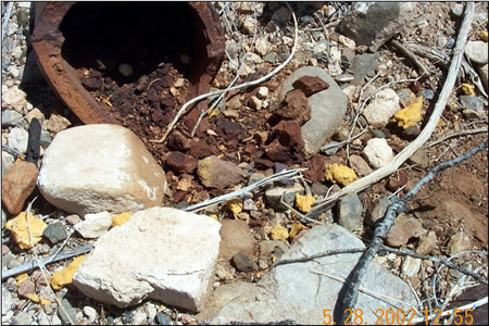
Wastewater from manufacturing operations is currently collected in holding tanks and treated using carbon adsorption columns. In the past, however, wastewater was often transported through pipes or ditches to unlined disposal ponds where particulates settled forming a sludge in which the explosive concentration could range into percent levels. Areas in the transport system where there were leaks in pipes or low spots in ditches also resulted in accumulation and subsequently high concentrations of residues in soils. In addition, synthesized material that was found to be below specification was often disposed at burning areas where this operation was often conducted directly on the soil. Heat from the burning process sometimes resulted in melting of the energetic material, which penetrated below the surface at burning grounds and resolidified sometimes leading to pure material in the shallow subsurface (Figure 3-1). Disposal operations were also conducted at DoD depots where out-of-date munitions were destroyed, often by either open burning or open detonation (OB/OD). Sometimes these operations resulted in deposition of residues of energetic materials as well.
| Figure 3.1. Subsurface re-crystallization of explosives found between burning trays at an ordnance works facility. Note: The orange-colored soil at the bottom of the pit contains percent levels of TNT. |
 |
The use of finished munitions at DoD testing and training ranges has also resulted in the deposition of residues of energetic compounds. The mass of residues deposited at these facilities is much lower than at manufacturing operations, but the dissolution and leaching of these residues has resulted in the suspension of training at one DoD facility.
Manufacturing Operations
Synthesis of TNT and 2,4-DNT in the United States was conducted at a number of ammunition plants, mostly located in the South and Midwest. In the past, TNT production involved a step-wise nitration of toluene with a mixture of nitric, sulfuric, and fuming sulfuric (oleum) acids. This crude TNT mixture underwent a two-step purification: the initial wash with warm water and soda ash (sodium carbonate) generated a highly acidic wastewater referred to as “yellow water”, and the second wash with cold water and sellite (sodium sulfite) generated an alkaline wastewater referred to as “red water”. Wastewater generated from these operations included the unsymmetrical isomers of trinitrotoluene, the various isomers of dinitrotoluene, trinitrotoluene, dinitrobenzene, and di- and trinitroxylene. For many years red water was reused by the dye industry until environmental regulations precluded this reuse. Because no satisfactory treatment alternative for this wastewater has been developed, the synthesis of TNT and 2,4-DNT in the United States was suspended in 1977 and no TNT or 2,4-DNT has been produced domestically ever since. Currently, all TNT used by the DoD is purchased from foreign sources. Residues resulting from the disposal of wastewater appear to be minor, however, in comparison to those produced from load, assemble, and pack operations.
RDX and HMX are synthesized in the United States at Holston Army Ammunition Plant (AAP) in Kingsport, Tennessee. The major impurities in the production of RDX and HMX are hexahydro-1-(N)-acetyl-3,5-dinitro-1,3,5-triazine (TAX) and octahydro-1-(N)-acetyl-3,5,7-trinitro-1,3,5,7-tetrozocine (SEX), respectively. Purification procedures remove these compounds to barely detectable concentrations in the final products. Deposition of residues of the RDX, HMX, TAX, and SEX from these operations appears to be small and limited to this one installation.
The synthesis of the nitrate esters such as NC, NG, PETN, and NQ has also been conducted at several ammunition plants. Generally these compounds were manufactured at different ammunition plants from those manufacturing munitions containing TNT and RDX. Some localized contamination at these facilities may be present, and the residues appear more of a safety hazard than an environmental concern. Much less work has been conducted at these facilities than at facilities where munitions containing TNT and RDX were manufactured.
Load, Assemble, and Pack (LAP) Operations
By far the largest mass of residues of explosives resulted from LAP operations at ammunition plants. Wastewater from the assembly of TNT- and Composition B-containing munitions is called “pink water” (because it turns pink to red in the sunlight) and contains a variety of explosives-related chemicals of which TNT and RDX predominate, in both the particulate and dissolved form. Currently these wastewaters are treated using carbon adsorption, but in the past they were disposed in unlined ponds. At a number of installations, groundwater plumes of RDX, in particular, are located below these ponds and migration of RDX has sometimes extended for miles down gradient (Spaulding and Fulton, 1988). Because TNT is sorbed to a greater extent by soils than RDX, TNT plumes are generally much smaller in size and the migration in groundwater is much slower.
DoD Testing and Training Ranges
The sampling of ranges for explosives residues is a fairly recent activity, with the first information published by Racine et al. in 1992, although some earlier work by the U.S. Army Environmental Hygiene Agency (now U.S. Army Center for Health Promotion and Preventive Medicine, USACHPPM) was conducted for water and sediments. Walsh et al. (2001) have summarized the early work in this area.
There are a number of different types of ranges that differ significantly in the types and concentrations of residues present in the soil. These include various types of Army ranges such as artillery and mortar ranges, hand-grenade ranges, 40-mm grenade ranges, demolition ranges, antitank-rocket ranges, and tank-firing ranges (often called multipurpose ranges), and Air Force ranges such as bombing ranges, rocket ranges, C-130 firing ranges, and demolition ranges. Very little information is available for Navy ranges.
Antitank-rocket ranges were the first type of range in which extensive characterization was conducted (Jenkins et al., 1997, 1998; Thiboutot et al., 1998; Pennington et al., 2002). These studies indicated that down-range HMX was the major contaminant (1 to >100 ppm) present with TNT present at concentrations about 1/100 of HMX. Contamination is largely present near the target and is due to LAW rockets (containing octol) that ruptured but did not detonate.
The concentrations of residues of explosives at artillery and mortar ranges are generally very low or below detection limits of the current methods except in areas next to targets or near rounds that underwent low-order (partial) detonations (Jenkins et al., 2001; Pennington et al., 2002; Ampleman et al., 2003). In the latter areas, concentration in soil can be in the percent level with chunk explosives sometimes visible at the surface (Pennington et al. 2003) (Figure 3-2). The major residues at these sites are TNT and RDX from TNT- and Composition B-containing munitions.
| Figure 3.2. Chunks of main charge, TNT, and remaining casing from the partial detonation of a 155-mm howitzer round found on an active artillery range. Note: Dark orange particles are chunks of TNT. |
 |
The residues present at hand-grenade ranges are largely due to training with M67 grenades containing Composition B (Jenkins et al., 2001). The major sources of residues at these ranges are hand grenades that undergo low-order (partial) detonations and unexploded grenades that are destroyed by EOD personnel using C4. Concentrations of TNT, RDX, and HMX have been detected at these ranges as high as the low ppm range.
Firing points for LAW rockets and various types of artillery and mortars have been investigated. The major residues are a function of the type of propellant used for the various weapon systems. For example, 2,4-DNT was found to be present in soil where 105-mm howitzers were fired (Jenkins et al., 2001; Walsh et al., 2003) because these propellants are single-based in which 2,4-DNT is used as a plasticizer with nitrocellulose. At the firing points on LAW-rocket training ranges, NG is the analyte found due to its use in the double-based propellant used for these rockets. NG is also the major residue found at 155-mm howitzer firing points because of its presence in the triple-based propellant used for this weapon system. Generally these residues from propellants are present in the ppb range except behind the firing line for LAW rockets where the NG concentration can be much higher (1 to >100 ppm) due to the back blast produced when these shoulder-fired weapons are used.
Air Force ranges have been studied to a much lesser degree than Army ranges. Training rounds that do not contain secondary explosives are used for many ranges and the levels of residues at these ranges are very low. One Canadian bombing range where live bombs are dropped has been studied and the major contaminant found in the soil was TNT in the ppm range (Ampleman, personal communication). This is consistent with the use of tritonal as the major explosive in Air Force bombs. Partial detonation of Air Force bombs has been observed at two ranges and this leads to very highly localized concentrations of TNT (Pennington et al., 2002; Ampleman, personal communication). Tritonal contains TNT and aluminum. Another potential source of contamination at Air Force ranges is rocket propellant, but research is lacking to assess the magnitude of this problem.
Disposal Operations
Numerous energetic compounds have been detected in soil samples collected on demolition ranges used for the OB/OD of UXOs and perhaps obsolete munitions (Hewitt et al., in prep). On a demolition range where there was evidence of recent activity, energetic residues in the 1 to 100 mg/kg range were detected for RDX, HMX, NG, 2,4-DNT, and TNT. However, TNB, 2-ADNT and 4-ADNT were also detected at lower concentrations (<1 ppm). Many of these same energetic compounds were found at similar concentrations in surface samples obtained from the demolition range at Camp Edwards Massachusetts Military Reservation (Jay Clausen, personal communication). These high concentrations and wide variety of energetic residues are consistent with residues detected after blow-in-place operations (Hewitt et al., 2003).
References
- Ampleman, G. Defence R&D Canada-Valcartier, personal communication.
- Ampleman, G., S. Thiboutot, R. Martel, R. Lefebvre, T.A. Ranney, T.F. Jenkins, and J.C. Pennington. 2003). Evaluating of the Impacts of Live Fire Training at CFB Shilo (Final Report). G. Defence R&D Canada-Valcartier Technical Report DRDC Valcartier TR 2003-066, April 2003.
- Clausen, J. AMEC Earth & Environmental, Inc. 239 Littleton Road, Suite 1B, Westford, MA, personal communication.
- Hewitt, A.D., T.F. Jenkins, T.A. Ranney, J.A. Stark, M.E. Walsh, S. Taylor, M.R. Walsh, D.J. Lambert, N.M. Perron, N.H. Collins, and R. Karn. 2003. Estimates for explosives residue for the detonation of Army munitions. U.S. Army Engineer Research and Development Center, U.S. Army Cold Regions Research and Engineering Laboratory, Hanover. ERDC/CRREL TR-03-16.
- Hewitt, A.D. et al. (in prep). Characterization of energetic residues at military firing ranges: Scholfield Barracks and Pohakulao Training Area, HI, Chapter 3 in Pennington, J.C. et al. Distribution and fate of energetics on DoD test and training ranges: Report 4, U. S. Army Engineer Research and Development Center, Environmental Laboratory, Vicksburg, MS. ERDC Technical Report.
- Jenkins, T.F., M.E. Walsh, P.G. Thorne, P.H. Miyares, T.A. Ranney, C.L. Grant, and J. Esparza. 1998. Site Characterization at the Inland Firing Range Impact Area at Ft. Ord. U.S. Army Cold Regions Research and Engineering Laboratory, Hanover, New Hampshire, CRREL Special Report 98-9.
- Jenkins, T.F., M.E. Walsh, P.G. Thorne, S. Thiboutot, G. Ampleman, T.A. Ranney, and C.L. Grant. 1997. Assessment of Sampling Error Associated with the Collection and Analysis of Soil Samples at a Firing Range Contaminated with HMX. U.S. Army Cold Regions Research and Engineering Laboratory, Hanover, New Hampshire, CRREL Special Report 97-22.
- Jenkins, T.F., J.C. Pennington, T.A. Ranney, T.E. Berry, Jr., P.H. Miyares, M.E. Walsh, A.D. Hewitt, N. Perron, L.V. Parker, C.A. Hayes, and Maj. E. Wahlgren. 2001. Characterization of Explosives Contamination at Military Firing Ranges. U.S. Army Engineer Research and Development Center, Hanover, New Hampshire. ERDC TR-01-05.
- Pennington, J. C., T. F. Jenkins, G. Ampleman, S. Thiboutot, J. M. Brannon, J. Lewis, J. E. Delaney, J. Clausen, A. D. Hewitt, M. A. Hollander, C. A. Hayes, J. A. Stark, A. Marois, S. Brochu, H.Q. Dinh, D. Lambert, R. Martel, P. Brousseau, N. M Perron, R. Lefebvre, W. Davis, T. A. Ranney, C. Gauthier, S. Taylor, and J. M. Ballard. 2003. “Distribution and fate of energetics on DoD test and training ranges: Report 3”, U. S. Army Engineer Research and Development Center, Vicksburg, MS, ERDC TR-03-2.
- Pennington, J.C., T.F. Jenkins, G. Ampleman, S. Thiboutot, J.M. Brannon, J. Lynch, T.A. Ranney, J.A. Stark, M.E. Walsh, J. Lewis, C.A. Hayes, J.E. Mirecki, A.D. Hewitt, N. Perron, D. Lambert, J. Clausen, and J.J. Delfino. 2002. Distribution and Fate of Energetics on DoD Test and Training Ranges: Interim Report 2., U. S. Army Engineer Research and Development Center, Vicksburg, MS, ERDC TR 02-8.
- Racine, C.H., M.E. Walsh, C.M. Collins, D.J. Calkins, B.D. Roebuck, and L. Reitsma. 1992. Waterfowl Mortality in Eagle River Flats, Alaska: The role of munitions residues. U.S. Army Cold Regions Research and Engineering Laboratory, Hanover, New Hampshire, CRREL Report 92-5.
- Spaulding, R.F., and J.W. Fulton.1988. Groundwater munition residues and nitrate near Grand Island, Nebraska, U.S.A. Journal of Contaminant Hydrology, vol. 2, p. 139-153.
- Thiboutot, S., G. Ampleman, A. Gagnon, A. Marois, T.F. Jenkins, M.E. Walsh, P.G. Thorne, and T.A. Ranney. 1998. Characterization of Antitank Firing Ranges at CFB Valcartier, WATC Wainwright and CFAD Dundurn. Defence Research Establishment Valcartier, Quebec, Report # DREV-R-9809, October 1998.
- Walsh, J.T., R.C. Chalk, and C.M. Merritt. 1973. Studies of Munition Wastes. Analytical Chemistry, vol. 45, p. 1215-1220.
- Walsh, M.E., C.M. Collins, C.H. Racine, T.F. Jenkins, A.B. Gelvin, and T.A. Ranney. 2001. Sampling for explosives residues at Fort Greely, Alaska. Reconnaissance visit July 2000. U.S. Army Cold Regions Research and Engineering Laboratory, Hanover, New Hampshire. ERDC/CRREL TR-01-15.
- Walsh, M.E., C.M. Collins, A.D. Hewitt, M.R. Walsh, T.F. Jenkins, J. Stark, A. Gelvin, T. Douglas, N. Perron, D. Lambert. R. Bailey, and K. Myers. 2004. Range characterization studies at Donnelly Training Area, Alaska: 2001 to 2002. U.S. Army Engineer Research and Development Center, Hanover, New Hampshire, ERDC/CRREL TR-04-3.
Safety
Safety Inspection and Clearance
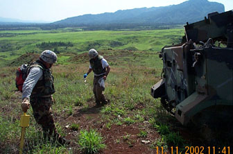
The first steps when planning a sampling campaign on a site potentially contaminated with explosives are to review all the historical information available and to perform a visual inspection of the area of concern. Sampling activities should only occur after performing these two initial tasks and obtaining the appropriate safety clearance for the sampling site. For example, many military firing ranges contain a significant amount of unexploded ordnance (UXO) on and below the surface. Prior to any sampling event for this type of site, clearance must be provided by explosive ordnance disposal (EOD) personnel who have the proper expertise and equipment (Figure 4.1). Once surface clearance has been performed (flagging area where UXO are suspected), care must still be taken, because highly contaminated soils (in excess of 10%) can propagate a detonation (Kristoff et al., 1987). Exposure of secondary explosives to heat, shock, impact, friction, and electrostatic charge can lead to violent reactions, including detonation, deflagration, and burning.
| Figure 4.1. EOD technician marking the position of a UXO. |
 |
Surface and Subsurface Sampling
At sites contaminated with explosives, sampling should first be carried out in the area that is suspected of having the highest concentration of energetic residues (Sisk, 1992). Moreover, only surface soil samples (0-5 cm) should be taken and no drilling should take place. If shallow-depth subsurface sampling is necessary, this task should be performed with extreme caution. This is a good example of where the field analytical methods can be very helpful. These tests can be performed rapidly, on-site to provide immediate information with respect to any potential risks. Both the colorimetric methods and immunoassay methods could be used to screen soil, however, since the colorimetric is less selective and has a greater dynamic working range it is better suited for this task (Crockett et al., 1994). Screening protocols that can be used with two commercially available colorimetric kits are presented in the screening technique section of this module (Jenkins et al., 1996; Hewitt et al., 2001). On-site colorimetric screening results can also inform the analyst of the need to dilute sample extracts in order to fall within the analytical range of the laboratory analysis method.
When energetic residue levels exceed 10% by weight of the sample, additional safety precautions must be implemented. The most important safety precaution is to minimize exposure, which involves reducing the number of workers exposed to the hazardous situation and limiting the duration of exposure on site. To reduce the hazard during the sample collection activity all mechanical operations should be carried out on materials that have been moistened with water. Water desensitizes the explosive to phlegmatizing by reducing potential to generate heat or friction while manipulating the sample. If operations involving mechanical shovelling are required, remotely controlled operations offer the best protection. When robotics are not available, armoured safety glass must be installed in the operator compartment, and operations should only be permitted after removing the soil layer that is contaminated above the safety level. Moreover, machinery used to acquire samples with high levels of energetic materials should have sealed bearings and shielded electrical junction boxes. This equipment should also be decontaminated frequently to prevent the build-up of explosives residues. Additionally, ungrounded plastic equipment and screw-top bottles should not be used for sample collection and storage of highly contaminated soil samples.
On military firing ranges, safety clearances can be performed at three different levels. Level-one clearance consists of identifying and/or removing surface UXOs. Level-two clearance consists of identifying and/or removing surface UXOs and screening the top 30-45 cm of soil for metal objects (i.e., potential UXOs) with the help of a hand-held magnetic detector. Level-three clearance involves completely clearing the area of the site of UXOs in the area where work is to be performed. This high-level clearance ensures the greatest safety and also allows the drilling of wells directly on the site. However, this operation is not generally economical and/or physically feasible. Therefore, often a level-two clearance that is capable of detecting metallic objects to profile depths of 1-2 m is obtained with the help of the proper equipment such as an electromagneto-meter. Monitoring wells can also be installed on a site that has been cleared with the level-two procedure, provided down-hole geophysical monitoring is conducted. Lastly, an EOD technician must be present at all times during the sampling operation to ensure that proper procedures are followed.
Shipping Requirements
Shipping of soils containing reactive levels of explosives using normal shipping procedures is prohibited. It has been determined that soils containing more than 12% (120,000 mg/kg) secondary explosive by weight can propagate a detonation (EPA 1993). To incorporate a small safety factor, a value of 10% is used in this regard. It should be noted that concentrations as high as 120,000 mg/kg of explosives residues are rarely encountered, and often a visual inspection will identify the presence of pure crystalline materials. These high levels have been found at old explosive production sites where production waste was dumped directly on the ground, in former lagoons used to contain wastewater at production facilities, around partially detonated munitions, and in areas where open burning / open detonation (OB/OD) of off-spec material and UXOs has been performed.
If screening of soil samples indicates that energetic materials are above the 10% limit, the contaminated material should be blended with background soil. This dilution is not a remedial action by itself, but a safety measure that will allow the safe handling, storing, and shipping of samples. Blending should be carried out precisely to calculate the initial concentration that was present in the sample. If the soil were not diluted, the transport of the samples would require the same safety waiver (manifested as a hazardous material and shipped according to DOT requirements for explosives) as that required for transporting pure secondary explosive material (AEC 1994).
References
- AEC. 1994. Standard comments for health and safety document review. Memorandum for record, SFIM-AEC-TSS, 18 July 1994, U.S. Army Environmental Center, Aberdeen Proving Ground, Maryland.
- Crockett A.B., T.F. Jenkins, H.D. Craig, and W.E. Sisk. 1998. Overview of on-site analytical methods for explosives in soil. U.S. Army Cold Regions Research and Engineering Laboratory, Hanover NH, Special Report 98-4.
- Environmental Protection Agency.1993. Handbook: Approaches for the remediation of federal facility sites contaminated with explosive of radioactive wastes. U.S. Environmental Protection Agency, Office of Research and Development, Washington, D.C., EPA/625/R-93/013.
- Hewitt A.D., T.F. Jenkins, and T.A. Ranney. 2001. Field Gas Chromatography / Thermionic Detector System for the Analysis of Explosives in Soils. U.S. Army Cold Regions Research and Engineering Laboratory, Hanover, NH, ERDC/CRREL TR-01-9.
- Jenkins, T.F., P.W. Schumacher, J.G. Mason, and P.T. Thorne. 1996. On-Site Analysis for High Concentrations of Explosives in Soil: Extraction Kinetics and Dilution Procedures. CRREL Special Report 96-10.
- Kristoff, F.T., T.W. Ewing, and D.E. Johnson. 1987. Testing to determine relationship between explosive contaminated sludge components and reactivity. USATHAMA Report No. AMXTH-TE-CR-86096, Aberdeen Proving Ground, MD.
- Sisk, W. 1992. Reactivity testing and handling explosives-contaminated soil, explosives and munitions. In Proceedings, 1992 Federal Environmental Restoration Conference, Hazardous Material Control Resources Institute, Vienna, p. 91-92.
Potential Applicable Criteria for Explosives
In addition to the hazards associated with the detonation of energetic compounds, there are toxicological considerations. Some of the secondary explosives are considered carcinogenic and mutagenic. The toxicity of explosive chemicals has been studied extensively by the U.S. Army Biomedical Research and Development Laboratory, and summaries of these investigations have been published (Rosenblatt, 1986; Burrows et al., 1989). For an indication of the toxicity of explosives on human health, Table 5.1 presents drinking water criteria for seven energetic compounds at a lifetime exposure cancer risk level of 10‑6.
For energetic compounds in soils the threshold levels are often evaluated on a site-by-site basis, depending on factors such as the proximity of the contaminated soils to other locations and the use of surrounding groundwater. Future use of the site is also taken into account. Risk based concentrations (Table 5.2), however, are available from the Environmental Protection Agency Region 3 to help provide guidance.
| Table 5.1. Lifetime Health Advisory for Drinking Water http://www.epa.gov/ost/drinking/standards/dwstandards.pdf |
|
| Compound | (µg/L) |
| TNT | 1.0 |
| RDX | 2.0 |
| HMX | 400 |
| 2,4-DNT | 0.17 |
| 2,6-DNT | 0.0068 |
| 1,3,5-TNB | 1.0 |
| NG | 5.0 |
| Table 5.2. Risk-Based Concentrations in Soil http://www.epa.gov/reg3hwmd/risk/index.htm |
||
| Analyte | Industrial (mg/kg) | Residential (mg/kg) |
| TNT | 95 | 21 |
| RDX | 26 | 5.8 |
| HMX | 51,000 | 3,900 |
| NG | 200 | 46 |
| 2,4-DNT | 2000 | 160 |
| 2,6-DNT | 1000 | 78 |
Other sources of information concerning drinking water standards and risk-based criteria can be found at the following sites:
- Testing to Determine Relationship between Explosive Contaminated Sludge and Reactivity, January 1987
- Region 3, Mid-Atlantic Risk-Based Concentration Table, October 2003
- Region 6 Human Health Medium Specific Screening Levels, January 2004
- Region 9, Preliminary Remediation Goals, October 2002 as modified February 2003
References
- Burrows, E.P., D.H. Rosenblatt, W.R. Mitchell, and D.L. Palmer. 1989. Organic explosives and related compounds: Environmental health considerations. US Army Biomedical Research and Development Laboratory; Report Number 8901, Fort Detrick, Frederick, MD.
- Rosenblatt, D.H. 1986. Contaminated soils cleanup objectives for Cornhusker Ammunition Plant. US Army Medical Bioengineering Research and Development Laboratory; Report Number 8603, Fort Detrick, Frederick, MD.
- Walsh, M.E., T.F. Jenkins, and P.G. Thorne. 1995. Laboratory and Field Analytical Methods for Explosives Residues in Soil; Proceedings of the Symposium on Alternatives to Incineration for Disposal of Chemical Munitions and Energetics, Vol. 2, p. 17.
Selecting an Appropriate Sampling Scheme
Technical Project (or Systematic) Planning
The investigation of any potentially contaminated site requires the development and implementation of a study plan that states the objectives of the work to be performed. Three of the issues that this study plan must address are the contaminants of interest, area(s) potentially contaminated, and the receptor(s) of concern. The area of interest could be an entire site or several defined areas (separate strata or populations) within a site. The receptors are plants, animals, or humans and the potential pathways of contaminant exposure: ingestion, inhalation, or dermal should be considered. Other issues that should be taken under consideration during the development of the study plan are site specific parameters such as the mode of contamination, the physical and chemical properties of the major potential contaminants that effect their fate and transport, and the geology and the hydro-geology of the site. The conceptual site model (CSM) is the day-to-day working tool that integrates all this information, along with knowledge about contaminant release and migration mechanisms, into a representation of the different contaminant populations likely present on a site. Distinctly different populations or strata can be created when distinctly different physical mechanisms of release or transport produce different contaminant distributions. At the level of project decisions, different populations often have different decision outcomes (e.g., soil areas needing no further action versus areas needing removal or treatment; choosing between one treatment/disposal option versus another). Project decision about characterization and cleanup can be much more cost-effective when different populations are reliably and clearly identified and delineated by the CSM. Collecting “representative data” often requires a two-stage process. If the preliminary CSM is uncertain about what populations are present and where, then data should be gathered to develop the CSM until it is complete enough to distinguish different decision-based populations or strata. Only then can a sampling design be developed that is appropriate to characterize those populations to estimate the characteristics of interest to the decision process (such as the population's variability and its mean). Within the context of an adaptive/dynamic sampling strategy, maturation of the CSM can proceed efficiently in real-time, as each cycle of data collection adds information that guides subsequent data collection events without needing multiple mobilizations. Real-time detection, delineation, and characterization of decision-based populations ensure that data will be representative of the intended decisions. Additional guidance on the information necessary to develop a study plan for a potentially contaminated site can be found in the “Conceptual site models for ordnance and explosives (OE) and hazardous, toxic, and radioactive waste (HTRW) projects” (U.S. Army Corps of Engineers, 2003). Once this information has been obtained, an appropriate sampling strategy can be selected to satisfy the project's decision-making objectives.
Sampling Design
The site should initially be divided into areas based on known or suspicion of contamination. These areas will likely require further segregation into areas (or strata) based on similar characteristics or the evaluation criteria of the data user. Once determined, the objective is to understand what information is needed about that population; how it will be represented by physical site samples; and what type of data can be obtained to evaluate site conditions from a spectrum of chemical analyses. When the objective is to estimate the statistical properties (such as the variability and mean) for a site or for a stratum within a site that is comprised of a single decision-based population, either an equiprobable (i.e., simple random) sampling or a systematic sampling design can be used. However, neither of these sampling schemes should be used if the CSM predicts that the area of interest contains substrata that are expected to have very different concentrations of the contaminants (i.e., different populations). For example, it would not be appropriate to include within a single stratum a drainage ditch or lagoon that was used to transfer or retain the contaminant of interest with areas where there is no previous history of contaminant exposure. Likewise, areas on military training ranges with fixed targets should be identified as separate strata from areas where there is no history of target placement (Figure 6.1). Failure to employ a properly stratified sampling scheme underestimates the influence of areas of potentially higher contamination or completely misses them altogether. Indeed, the chances of missing locations of elevated contamination increases proportionally with size discrepancy between the stratum and the substratum within that area that has higher contaminant levels. As more strata are identified within an area, the more segregated the contaminant populations become, and, subsequently, the sampling scheme changes from one that is based on probability to authoritative. Coupling an authoritative (i.e., judgmental) sampling scheme with sufficient knowledge of the mode of contamination often is very useful when the objective is to rank potential source strengths. Once the source strengths (mass loading) for different strata have been determined, predictive models can be used to predict the exposure level for a given receptor.
| Figure 6.1. Cluster of targets located on an active impact range. |
 |
Once the different strata have been identified, either a simple random or systematic sampling scheme can be used for the sample collection process. A systematic design (location of sample collection is predetermined) is used when assessing if spatial patterns exist (gradients in concentration) or for establishing if there are trends. A simple random sampling design provides a statistically unbiased approach because every unit has an equiprobable chance of being collected. The number of samples that should be collected in a chosen stratum should be determined empirically. Therefore, as part of the sampling plan a predetermined number of field-sample replicates should be obtained to assess if the uncertainty among the concentration estimates is within a range that is acceptable to the project's decision-making objectives.
Likewise the number of increments collected to build a composite sample should be empirically determined for a given stratum. Our experience has been that the distribution of discrete samples for energetic compounds is never sufficiently normal to justify the use of normal distribution statistics. However, multi-increment composite samples are often distributed normally if a sufficient number of increments are collected for each composite. Generally, 30 increments are adequate in this regard. The module on collecting a representative soil sample further addresses the strategies that can be used to collect soil samples that support project decisions.
References
- U.S. Army Corps of Engineers. 2003. Conceptual Site Model for Ordnance ad Explosives (OE) and Hazardous, Toxic, and Radioactive Waste (HTRW) Projects: EM 1110-1-1200. Washington, DC.
Collecting a Representative Soil Sample
- Sample Depth
- Discrete vs. Composite Sampling
- Subsurface Sampling
- Sample Size
- Sampling Tools and Supplies
- Sampling Areas where Chunks ofEnergetic Residues are Present
- References
Sample Depth
The unusual nature of energetic compounds as contaminants should be taken into consideration prior to developing a field-sampling plan. Explosives are solids at ambient temperature, and they are often dispersed as various sized and shaped particles that slowly dissolve in precipitation because they are sparingly soluble and are only wetted on a periodic basis. They also possess low vapor pressures and hence do not volatilize to any extent (Table 2.1). Their distribution is typically very heterogeneous, and they are only transported through soil after they are dissolved in water. Hence, the highest levels of explosive contamination are most likely to occur on or near the soil surface, unless the soil has been moved or filled, even at sites that have remained dormant for many years. We recommend that when the explosives residues are dispersed as particles (i.e., impact ranges, demolition range, firing points) the sampling depth should be limited to the near surface (0-5 cm). The more common 0- to 15-cm sampling depth, however, may be appropriate for locations where explosive residues are in a dissolved state when they are introduced into the environment. Nevertheless, the spatial distribution of residues will vary, depending upon the manner in which the contamination occurred, the specific target compound, and the nature of the soil matrix. For these reasons, subsurface soil sampling may be necessary to delineate the transport pathway or the contamination plume.
Discrete vs. Composite Sampling
The major objective of any sampling plan is to obtain samples that are representative of the property or characteristic used as the basis of project decision-making. For some decisions, the desired property of interest is an estimate of the mean over a given area, or for a single distinct population or stratum. For other decisions, the extent of contamination may be desired, requiring a data set that shows that the boundaries of contamination have been located. In other cases, data is used to guide decisions about cleanup strategies or disposal options, requiring data sets that estimate the volumes of contaminated material categorized by concentration and other matrix characteristics determining migration potential or cost-effective treatment options. Different decision goals require data sets with different representativeness. During systematic project planning, the spatial, temporal, and other scales relevant to individual project decisions are clarified. During sampling-plan development, the scales of data collection are designed to match the scales of decision-making. The goals of data collection are used to decide the scales (such as scales of space, particle size, and occasionally, time) over which the impact of contaminant variability must be controlled to provide meaningful information to the decision-making process. For extremely heterogeneous matrices (such as soils contaminated by explosives residues) matching the scale of data collection to the scale of decision-making requires careful planning that considers all steps in the sample collection, handling and processing chain. Variables that impact the representativeness of analytical results, such as the sample volume and orientation, homogenization procedures, subsample volume, and particle size must be controlled when dealing with matrices that are heterogeneous at both macro and micro scales.
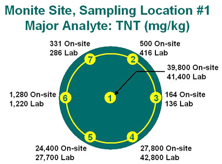
This implies that the concentration determined for the sample will provide a valid estimate of the average concentration for the specified area of concern. Therefore, it is imperative that the area of concern be defined prior to designing a sampling plan. Two typical scenarios are the identification of a suspected surface hot spot and establishing the average surface concentration of explosives residues over a specified area. In the past, sampling plans for each of these cases were written for the collection of discrete samples at a specified number of sampling locations. However, several studies have shown the futility of this practice, due to extreme short-range spatial variability that often exists for explosives in surface soils (Walsh et al., 1993; Jenkins et al., 1996a; Jenkins et al., 1997a; Jenkins et al., 1997b; Thiboutot et al., 1997; Jenkins et al., 1997c) (Figure 7.1).
| Figure 7.1. Example of spatial distribution of energetic residues in surface soils. Samples taken around and in the middle of a 1-meter diameter circle. Note spatial distribution is much greater than variation in concentrations established by a field and laboratory analytical method. |
 |
As a consequence, multi-increment composite sampling is strongly recommended when characterizing the ground surface at a site potentially contaminated with explosives or propellants. In a small area (1 m x 1 m), multiple units (10 or more, each of the same approximate amount) should be systematically or randomly collected and placed into a single container. For larger areas, systematic gridding is useful for establishing sampling nodes, at which an area of between 3- and 10-m diameter could be systematically or randomly sampled by obtaining 30 or more individual increments (Figure 7.2). Another approach that can be used if the area of concern isn't too large (100 x 100 m) is the collection of a large composite sample by obtaining the increments at established grid nodes (intervals) or at random intervals while walking around the entire site. Consult “Statistical Method for Environmental Pollution Monitoring” (Gilbert, 1987) for selecting the appropriate sampling design, i.e., grid spacing, to meet decision confidence goals for various project decisions.
| Figure 7.2. Collection of a multi-increment composite sample around a target on an active impact range. |
 |
Subsurface Sampling
With the exception of coupling soil profile sampling with the installation of groundwater sampling points, subsurface (vadose zone) sampling should only occur after the identification of a surface hot spot (including disposal lagoons, unlined burning pits). Beneath a hot spot it is recommended that a continuous vertical profile be collected over the first meter, with the profile broken into several (5 or more) increments, and each increment individually processed for analysis. Beneath 1 m, samples can be collected at larger intervals.
Sample Size
For each sample, a minimum of 500 g of soil should be collected and stored at a low temperature (typically less than 4 °C) until being processed for analysis. One exception is when performing profile sampling. In this case, the dimensions of the drilling equipment and the interval of concern may limit the sample size. The surface interface of training ranges is particularly important because both propellant and secondary explosives residues are distributed as particles during projectile firing and ordnance detonation. In some cases this means that leaf litter, moss, and grasses should be considered as part of the sample. These various forms of vegetation have traditionally been scraped away prior to the collection of a soil sample when performing environmental investigations.
Sampling Tools and Supplies
Typically, soil samples can be collected using either metal or rigid plastic tools. One exception is when energetic residues exceed 12% w/w of the medium being sampled. In these infrequent situations special sampling protocols, equipment, and storage vessels are recommended to help insure sampler safety. The collection tool used often depends on the cohesiveness, coarseness, and moisture content of the soil, and the vegetative surface cover. In general, when sampling a sandy soil with sparse vegetation, hand-held metal or plastic scoops work well. For more consolidated soils with a vegetated surface, a tool similar to a bulb planter works well.
When shallow depth sampling is necessary, a metal corer (stainless steel hand corer) that is manually pushed or driven into the ground can be used. Generally, mechanically driven sampling equipment will be necessary when sampling at depths greater than a meter. All of the equipment that comes into contact with the soil should be carefully wiped with a clean paper towel to remove soil, rinsed with water and then with acetone, and air-dried between sampling locations.
Clean polyethylene plastic bags or glass jars should be used as containers while collecting soil samples in the field and for storage prior to and after subsampling. Immediately after collection the samples should be cooled and stored in the dark (e.g., in ice coolers).
Sampling Areas where Chunks of Energetic Residues are Present
When “chunks” of energetic residues are visibly present the subsequent samples collected to assess the surface soil concentrations should be specially marked. Furthermore these samples should be collected with separate sampling equipment and stored in separate shipping containers than all other samples. Taking these measures will help to prevent cross contamination between sample during field operations and transport. Most importantly, these samples should be marked to alert laboratory personnel that they should remain isolated from the other field samples throughout the entire preparation protocol.
References
- Gilbert, R.O. 1987. Statistical Methods for Environmental Pollution Monitoring. Van Nostrand Reinhold, New York, NY.
- Jenkins, T.F., C.L. Grant, G.S. Brar, P.G. Thorne, P.W. Schumacher, and T.A. Ranney. 1996a. Assessment of Sampling Error Associated with the Collection and Analysis of Soil Samples at Explosives Contaminated Sites. U.S. Army Cold Regions Research and Engineering Laboratory, Hanover NH, Special Report 96-15.
- Jenkins, T.F., C.L. Grant, G.S. Brar, P.G. Thorne, P.W. Schumacher, and T.A. Ranney. 1997a. Assessment of Sampling Error Associated with the Collection and Analysis of Soil Samples at Explosives Contaminated Sites. Field Analytical Chemistry and Technology, vol. 1, p. 151-163.
- Jenkins, T.F., M.E. Walsh, P.G. Thorne, S. Thiboutot, G. Ampleman, T.A. Ranney, and C.L Grant. 1997b. Assessment of Sampling Error Associated with Collection and Analysis of Soil Samples at a Firing Range Contaminated with HMX. U.S. Army Cold Regions Research and Engineering Laboratory, Hanover NH, Special Report 97-22.
- Jenkins, T.F., P.G. Thorne, M.E. Walsh, C.L. Grant, S. Thiboutot, G. Ampleman, T.A. Ranney, and M.H. Stutz. 1997c. Sampling Strategy for Site Characterization at Explosives-Contaminated Sites. Proceedings of the Second Tri-service Environmental Technology Workshop, St.-Louis, Missouri.
- Thiboutot, S., G. Ampleman, T.F. Jenkins, M.E. Walsh, P.G. Thorne, T.A. Ranney, and G.L. Grant. 1997. Assessment of Sampling Strategy for Explosives-Contaminated Soils. Proceedings of the 90th Annual Air & Waste Management Meeting, Paper 94-WP 101.08, Toronto.
- Walsh, M.E., T.F. Jenkins, P.S. Schnitker, J.W. Elwell, and M.H. Stutz. 1993. Evaluation of Analytical Requirements Associated with Sites Potentially Contaminated with Residues of High Explosives. U.S. Army Cold Regions Research and Engineering Laboratory, Hanover NH, CRREL Report 93-5.
Groundwater Sampling
- Introduction
- Considerations When Sampling Explosives
- Thief-Type Samplers
- Discrete-Interval Pump Samplers
- Low-Flow Sampling
- Passive Diffusion Samplers
- Sample Collection, Handling, and Storage
- References
Introduction
Over the last decade, groundwater-sampling techniques have been the topic of intense scrutiny with respect to representativeness and the effect of various methods and equipment on sample quality. The reason for this concern is the growing awareness that contamination can be strongly localized to certain discrete stratigraphic layers. When this kind of heterogeneity is present, the placement and length of the well screen and the degree of mixing (e.g., through purging) across different layers is a strong determinant of the contaminant concentrations in the groundwater sample. The misleading data that is produced when sampling-related variables are uncontrolled easily creates inaccurate CSMs and faulty decisions about exposure and remedial design. In general, the intended decision should guide the design of sampling procedures so that the data produced are representative of the decision. For example, sample collection for data representative of a drinking water scenario would properly mirror the mixing that occurs in a drinking water well, but sample collection geared to developing an accurate CSM to support source detection and remedial design would avoid that mixing. Currently, a low-flow purging and sampling protocol, with minimal drawdown and dedicated pumps (Puls and Barcelona, 1996; EPA Region 1, 1996; Nielsen and Nielsen, 2002; ASTM, 2003), is commonly used. In addition, more emphasis is being placed upon discrete-interval sampling (profiling contamination with depth in a well) and using shorter screens in monitoring wells. The need to purge a well prior to sampling is another issue that is currently being debated. This section presents general information about several different types of groundwater samplers without specifying equipment-unique sampling protocols. In general, when the principle objective is to establish the presence or absence of explosives, sampling can be performed using a variety of fairly simple techniques. Because the most important factor in this instance is cross contamination between sampling points, it is advisable to use dedicated or disposable devices. When groundwater sampling is being used to monitor spatial and temporal trends within a contaminant plume, the sampling protocol needs to enhance the ability of the samples to represent the local concentrations in the formation. Under these circumstances, a much more stringent protocol, which is consistent with both the project decision goals and equipment to be used, needs to be specified.
Considerations When Sampling Explosives
Because of the physical properties of explosives, they do not readily volatilize from solution or dissociate in solution (i.e., form charged species). They are also relatively hydrophilic and thus do not tend to sorb or partition into organic matter. Thus, we would expect that these analytes would not have a great affinity for other solid phase materials, particulates, or colloids. Therefore, high turbidity in samples, mobilization of colloids during sampling, and colloidal transport in groundwater are not significant issues when sampling for explosives.
Because of the tendency of explosives to stay in solution, obtaining sample results representative of the total environmental loading is less problematic than for metals and other organics such as volatile organic compounds (VOCs) and highly hydrophobic compounds (e.g., polycyclic aromatic hydrocarbons). Thus, it may be possible to use less stringent sampling methods than the currently accepted low-flow sampling protocol when sampling exclusively for explosives, depending upon the analytical requirements, site conditions, and regulatory guidelines and requirements.
Despite the conservative behavior of most explosives in solution, there is evidence that substantial quantities of production by-products (e.g., nitrotoluenes and nitrobenzene) are sorbed by most polymers used in sampling (e.g., polyethylene and polypropylene), and that Teflon fluoropolymers are the least sorptive (tubing) materials tested (Parker and Ranney, 1997). While there is not a lot of data on the sorption of explosives by polymers per se, it has been shown that sorption is minimal for less sorptive materials such as rigid polyvinyl chloride (PVC) and polytetrafluoroethylene (Parker and Ranney, 1994). Therefore, more sorptive materials should be given time to equilibrate with the groundwater to reduce losses due to sorption. For tubing, some equilibration occurs normally during the purging process; the time required for equilibration will depend upon the analyte, tubing material, length of tubing, and flow rate (Parker and Ranney, 1998).
Thief-Type Samplers
| Figure 8.1. HydraSleeve sampler. |
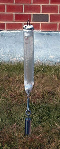 |
Typically, grab- or thief-type samplers are easy to use, allow quick and relatively inexpensive sampling, and can be used to sample deeper wells and a variety of analytes. Older thief-type devices used for groundwater sampling include bailers and syringe samplers. Although commonly used, bailers typically require that the well be purged, and they have been shown to agitate the water in the well, aerate samples during sample collection and transfer, and undergo depressurization when raised from deep wells (thereby affecting the chemistry of some samples). Therefore, these older devices are reported to be best suited for sampling contaminants, such as explosives, that are not volatile and are not readily oxidized and subject to precipitation reactions. Newly developed thief-type devices have been designed to sample discrete levels within a well and may not require the well to be purged. These devices include the HydraSleeve (GeoInsight) (Figure 8.1) and Kabis (SIBAK Industries Ltd., Inc) samplers.
The HydraSleeve sampler consists of a flexible polyethylene sleeve with a polyethylene check ball at the top. The device is left in the well overnight to equilibrate and then filled by being moved up and down several times. This device has been shown to recover concentrations of explosives from a standpipe that are representative of the dissolved, uniform concentration present in the test standpipe (Parker and Clark, 2002). This device has recently been redesigned so that it can be filled in a single pull, which should greatly reduce any disturbance of the well by the device during sampling.
The Kabis sampler is a bullet-shaped, stainless-steel device that holds a sample bottle. The inlet and exhaust ports are designed to prevent the device from filling as it is lowered into the well. Once it remains stationary for a few seconds, the device fills and the sample container(s) is rinsed several times with well water prior to collecting the final sample. Although Parker and Clark (2002) found that they could recover representative concentrations of explosives from a test standpipe with this device, Einfeld and Koglin (2000) found that this device either entrained contaminants or collected a partial sample as it was lowered through the water column.
Pressurized thief-type samplers use positive pressure while the device is raised and lowered to achieve discrete level sampling. Reported advantages include being able to: 1) sample a broad variety of analytes; 2) profile concentrations gradients with depth; 3) sample deeper wells; 4) sample with little or no purging; and 5) recover a sample that is under the same pressure and redox conditions that exist in the well. Commercially available devices include the Discrete Interval Sampler (Solinst Canada Ltd.) and the Pneumo-Bailer (Best Environmental Subsurface Sampling Technologies, Inc.). In a lab study, both devices were shown to recover concentrations of explosives representative of the uniform concentrations present in the test container (Parker and Clark, 2002).
Discrete-Interval Pump Samplers
The Easy-Pump™ Direct Purge and Sample System (Voss Technologies, Inc.) isolates the water column above the screened interval with an inflatable bladder and then pumps water from the screened interval into the water column above the well screen, thereby eliminating the cost of disposal of purge water. We are unaware of any studies that have evaluated this system for use in the collection of samples for explosives analyses.
The multi-level sampler (Solinst Canada, Ltd.), also known as the continuous multi-channel tubing (CMT) system, consists of a length of multi-channel tubing with up to seven sampling ports that can be positioned at various depths within the well screen (Einarson and Cherry, 2002). Typically, the individual channels are sampled using a peristaltic pump, although a 3/8-inch bladder pump (Solinst Canada, Ltd.) has recently been developed. For deeper wells, small-diameter bailers, inertial lift pumps, and small-diameter canister samplers have also been used.
Although neither of these systems has been evaluated for sampling explosives, presumably both could be used for sampling explosives.
Low-Flow Sampling
The purge parameters commonly used with low-flow sampling are temperature, conductivity, and dissolved oxygen to determine when concentrations have stabilized and purging is no longer required. Moreover, while purging groundwater the flow rate should be controlled so as to limit a water level draw down. When the sampling depth is less than 25-ft (7.6 m), a suction lift pump can be used, while a submersible pump is recommended for greater depths. Measurements are taken at time intervals (3 to 5 min.) or after successive half-well volumes. When the appropriate parameter(s) has stabilized (agrees within 10% of each other for three consecutive measurements) and sufficient water has been purged from the well, a groundwater sample can be collected. The positioning of sample inlet (collection point), water quality stabilisation parameters, and flow rate should be recorded for each sampling event. Moreover, the sampling team should strive to match each of these parameters during all subsequent sampling events.
Passive Diffusion Samplers
With passive diffusion devices, contaminants permeate a polymeric membrane into a chamber initially filled with distilled or deionized water. Diffusion continues until equilibrium is reached. Because no water is drawn into the well via pumping, water is not pulled from other parts of the formation. These devices have been used to profile contamination in a well with depth and can be used to collect samples in formations with low permeability (Robin and Gillham, 1987). Under a hydrological regime where vertical flow inside the well in insignificant, mixing of water between different depth zones is avoided. For some contaminants, stratification of concentrations with depth can be severe. Uncontrolled mixing between stratified zones can introduce large variability into data. Since depth-discrete samplers avoid mixing between high and low concentration zones, the analytical data are representative of contaminant concentrations in the immediate vicinity of the sampler. A vertical string of samplers down a well preserves information about vertical stratification in the well. This information can be critical to support development of an accurate CSM that guides correct decisions about contaminant fate, migration, and treatment.
Currently, two types of diffusion samplers are commercially available: the passive diffusion bag (PDB) sampler (marketed by Columbia Analytical and Eon Products) and the Multilevel Sampler (MLS) (sold in the U.S. by Johnson Well Screens, Inc.). The PDB sampler consists of a polyethylene bag and was developed for sampling VOCs (Vroblesky and Hyde, 1997; Vroblesky, 2001). This sampler should not be used for sampling explosives (Parker and Clark, 2002). The DMLS consists of a PVC rod that contains 20-mL polyethylene cells with dialysis membrane covered end caps. The DMLS has been used to sample anions, dissolved gases, and VOCs (Ronen et al., 1986; Magaritz et al., 1989; Kaplan et al., 1991) but has not been tested for sampling explosives. However, the small sample volume collected with this device limits its use for explosives.
Sample Collection, Handling, and Storage
Groundwater containing explosives should be collected in amber glass bottles to prevent photodegradation. For low concentrations (ppb levels), a 1-liter bottle is required. The sample does not need to be filtered but should be acidified to a pH of 2 using sodium bisulfate (Jenkins et al., 1995) and kept cold (4°C). Because of the relatively low solubility of explosives in water, there are no special safety concerns associated with shipping groundwater samples containing explosives.
References
- ASTM. 2003. Standard Practice for Low-Flow Purging and Sampling for Wells and Devices Used for Ground-Water Quality Investigations. ASTM International, West Conshohocken, PA. ASTM Standard D 6771, 7 pp.
- Einarson, M.D. and J.A. Cherry. 2002. A new multilevel ground water monitoring system using multichannel tubing. Ground Water Monitoring and Remediation, vol. 22(4), p. 52-65.
- Einfeld, W., and E.N. Koglin. 2000. Environmental Technology Verification Report: Groundwater Sampling Technologies, Sibak Industries Ltd., Inc. Kabis Sampler Models I and II. US Environmental Protection Agency, Office of Research and Development, Washington, D.C., EPA/600/R-00/054.
- Jenkins, T.F., P.G. Thorne, E.F. McCormick, and K.F. Myers. 1995. Preservation of Water Samples Containing Nitroaromatics and Nitramines. US Army Cold Regions Research and Engineering Laboratory, Hanover, NH. Special Report 95-16.
- Kaplan, E., S. Banerjee, D. Ronen, M. Magaritz, A. Machlin, M. Sosnow, and E. Koglin. 1991. Multilayer Sampling in the Water-Table Region of a Sandy Aquifer. Ground Water, vol. 29(2), p. 191-198.
- Magaritz, M., M. Wells, A.J. Amiel, and D. Ronen. 1989. Application of a multi-layer sampler based upon the dialysis cell technique for the study of trace metals in ground water. Applied Geochemistry, vol. 4, p. 617-624.
- Nielsen, D.M., and G.L. Nielsen. 2002. Technical Guidance on Low-Flow Purging and Sampling and Minimum-Purge Sampling: Second Edition. Nielsen Environmental Field School Publication NEFS-TG001-02. 59 pp.
- Parker, L.V., and C.H. Clark. 2002. Study of Five Discrete Interval-Type Groundwater Sampling Devices. US Army Corps of Engineers, Engineer Research and Development Center, Cold Regions Research and Engineering Laboratory, Hanover, NH. ERDC/CRREL TR-02-12.
- Parker, L.V., and T.A. Ranney. 1994. Effect of Concentration on Sorption of Dissolved Organics by Well Casings. Ground Water Monitoring Review, vol. 14(3), p. 139-149.
- Parker, L.V., and T.A. Ranney. 1997. Sampling trace-level organic solutes with polymeric tubing: I. Static studies. Ground Water Monitoring and Remediation, vol. 17(4), p. 115-1124.
- Parker, L.V., and T.A. Ranney. 1998. Sampling Trace-Level Organics with Polymeric Tubing: Part 2. Dynamic Studies. Ground Water Monitoring and Remediation, vol. 18(1), p. 148-155.
- Puls, R.W., and M.J. Barcelona. 1996. Low-flow (Minimal Drawdown) Ground-Water Sampling Procedures. United States Environmental Protection Agency, Office of Research and Development, Office of Solid Waste and Emergency Response, Washington, D.C., EPA/540/S-95/504.
- Robin, M.H., L. and R.W. Gillham. 1987. Field Evaluation of Well Purging Procedures. Ground Water Monitoring Review, vol. 7(4), p. 85-93.
- Ronen, D., M. Magaritz, and I. Levy. 1986. A Multi-layer sampler for the study of detailed hydrochemical profiles in groundwater. Water Research, vol. 20(3), p. 311-315.
- Environmental Protection Agency Region I. 1996. Low Stress (low flow) Purging and Sampling Procedure for the Collection of Ground Water Samples From Monitoring Wells, Revision 2. U.S. Environmental Protection Agency Region I Boston, Massachusetts, US EPA Region I SOP # GW 0001.
- Vroblesky, D.A. 2001. User's Guide for Polyethylene-Based Passive Diffusion Bag Samplers to Obtain Volatile Organic Compound Concentrations in Wells. Part 1. Deployment, Recovery, Data Interpretation, and Quality Control and Assurance. US. Geological Survey, Water-Resources Investigations Report 01-4060.
- Vroblesky, D.A. and W.T. Hyde. 1997. Diffusion Samplers as an Inexpensive Approach to Monitoring VOCs in Ground Water. Ground Water Monitoring and Remediation, vol. 17(3), p. 177-184.
Sample Preservation
Soil/Sediment Samples
For soil samples, Method 8330 specifies a maximum pre-extraction holding time (MHT) of seven days in the dark at 4 °C for nitramines and nitroaromatics. However, studies have shown that nitramines are stable over an eight-week period when held at 4 °C in the dark, and that nitroaromatics are stable for the same period when frozen (Grant et al., 1993a; Jenkins et al., 1994). In the field, soil or sediment samples should be placed in a cooler packed with ice or with another refrigerant soon after collected. Once the laboratory receives them, the samples should either be frozen or immediately spread out on clean surface to air dry. Once air-dried the need to refrigerate no longer is critical for short periods (days to weeks), however, long-term storage at 4 °C or lower, is recommended. Following extraction with acetonitrile, the analytes are stable if held in a vapor tight container. Refrigeration of extracts in amber glass bottles with Teflon lined septa is recommended for long-term storage of sample extracts.
Water Samples
For water samples, Method 8330 specifies a maximum pre-extraction holding (MHT) time of seven days in the dark at 4 °C for nitramines and nitroaromatics. Studies have evaluated the pre-extraction holding times for nitroaromatic and nitramine explosives (Maskarinec et al., 1991; Grant et al., 1993b) and the preservation of water samples (Jenkins et al., 1995). The first two studies demonstrated that MHT of 50 days could be used for both nitramines and nitroaromatics in many types of water samples when refrigerated at 4 °C. However, water with active microbial populations (such as surface water) showed significant losses of TNB and TNT within a day or two, when refrigerated at 4 °C. The preservation study concluded that the MHT for water samples containing nitroaromatics such as TNT, TNB, and tetryl can be extended to at least 28 days by acidification to pH 2 using NaHSO4 (e.g., 1.2 g / 1 L). Furthermore, the acidification did not affect the stability of nitramines that were already stable over a period of 50 days, with or without preservation. Therefore, all water samples should be acidified to pH 2 (or less) soon after collection. In the field this can be accomplished by adding the appropriate amount (weight) of NaHSO4 to the water sample. Once acidified, they should be stored in the dark at 4 °C. Under these conditions, water samples can be held up 28 days prior to extraction.
References
- Grant, C.L., T.F. Jenkins, and S.M. Golden. 1993a. Experimental Assessment of Analytical Holding Times for Nitroaromatics and Nitramines Explosives in Soils. US Army Cold Regions Research and Engineering Laboratory, Hanover, NH. Special Report 93-11.
- Grant, C.L., T.F. Jenkins, and S.M. Golden. 1993b. Evaluation of Pre-Extraction Analytical Holding Times for Nitroaromatics and Nitramines Explosives in Water. US Army Cold Regions Research and Engineering Laboratory, Hanover, NH. Special Report 93-24.
- Jenkins, T.F., C.L. Grant, K.F. Myers, and E.F. McCormick. 1994. Preextraction Holding Times for Nitroaromatics and Nitramines in Soils; 10th Annual Waste Testing and Quality Assurance Symposium, Arlington, Virginia, pp. 462-472.
- Jenkins, T.F., P.G. Thorne, E.F. McCormick, and K.F. Myers. 1995. Preservation of Water Samples Containing Nitroaromatics and Nitramines. US Army Cold Regions Research and Engineering Laboratory, Hanover, NH. Special Report 95-16.
- Maskarinec, M.P., C.K. Bayne, L.H. Johnson, S.K. Holladay, R.A. Jenkins, and B.A Tomkins. 1991. Stability of Explosives in Environmental Water and Soil Samples. Oak Ridge National Laboratory, Report ORNL/TM-11770.
Representative Subsampling of Soil Samples
Introduction
Because only a small portion (subsample) of the 500-g or larger sample of soil is extracted for analysis, the bulk sample must be thoroughly mixed so that the subsample is representative of the average concentration for the entire original sample. The following steps are typically involved to mix a bulk material for the analysis of semi-volatile organic compounds: air-drying, subjective removal of the vegetation and larger pebbles, grinding, sieving, and mixing. When Method 8330 (http://www.epa.gov/waste/hazard/testmethods/sw846/pdfs/8330a.pdf) was developed the majority of sampling activities were occurring at manufacturing, LAP, and demilitarization facilities. These facilities used large quantities of water daily to help keep the equipment safe for operation. Therefore, energetic compounds were often dissolved before they came in contact with the environment, i.e., drainage ditches, holding ponds, etc. In a dissolved state, residues would tend to accumulate on soil particles with the greatest surface area (i.e., smaller size). This mechanism of distribution is very different from those that occur on a military testing and training range (i.e., firing range), where residues of energetic compounds are dispersed as particles of various sizes. Based on the findings in a recent study, a large fraction of the energetic residues can go unaccounted for when samples are processed following the guidelines in Method 8330 (Hewitt et al., in prep).
Soil-Sample Mixing and Subsampling
Independent of where the soil sample is collected, the first step should be to air dry it at room temperature by spreading the sample out on a clean flat surface in a room that has limited sunlight. Marked samples collected in areas where chunks of energetic residues were present should be dried in a separate room. Moreover, any subsequent sample processing (i.e., grinding, subsampling) should be performed only after extreme precautions have been taken to prevent cross contamination. Indeed, it is a good practice to hold out these samples until all of the other samples have been processed, and to use dedicated equipment for these special samples. If the soil sample is from a location where it was likely to have been distributed in the dissolved phase, it can be processed following Method 8330:
- clumps of soil in the sample are broken up in a mortar and pestle,
- the sample is passed through a 30-mesh sieve (0.60-mm),
- the sieved fraction is mixed,
- and a 2-g subsample is removed for extraction with 10 ml of acetonitrile.
When the soil sample is from a military training range:
- The sample should be passed through a 10-mesh sieve (2.0-mm) after drying. This larger-size sieve allows all particles of energetic compounds that are less than 2 mm in diameter to be processed for analysis.
- Following sieving, the entire soil sample should be mechanically ground in a ring and puck mill for 60 seconds if it is vegetation free and 90 seconds if vegetation is present. Once mechanically ground, the entire sample will have the consistency of flour, i.e., the majority passes a 200-mesh (0.075-mm) sieve (Figure 10-1).
- The ground sample should be thoroughly mixed, then spread out in a thin layer and multiple units (30 or more) taken from random locations to build a subsample. A 10-g subsample is recommended, which should be extracted with twice the volume (e.g., in this case 20 ml) of acetonitrile.
| Figure 10.1. Soil sample after being ground for 60 seconds in ring and puck mill. |
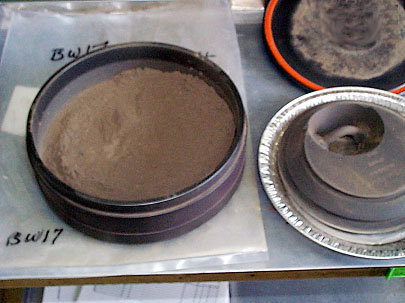 |
Subsampling Concerns
Care should be taken when collecting each unit so that particles of all sizes are represented in the same proportions; that is, a visual inspection should establish similar particle size distributions for both the subsample and the bulk sample. An alternative method of obtaining subsamples following grinding is to use a rotary sample divider. This approach to preparing a sample for laboratory subsampling has been shown to be very effective for those explosives that are crystalline; however, subsampling error remains a factor of concern for energetics associated with propellants. The particles generated from the burning or detonation of propellants are often fibers (1 to 2 mm in length) that retain the physical characteristics of nitrocellulose, and, therefore, are more pliable (malleable) than grains of soil or crystalline explosives.
A note of caution for samples from military training ranges is that prior to grinding it is advisable to screen the bulk sample for high levels (chunks) of explosives residues. Sample grinding is not recommended when screening results indicated explosive residue concentrations greater than 1,000 mg/kg. When using either method of preparing a sample for subsampling, it is recommended that several laboratory replicates be taken so that subsampling representativeness can be properly evaluated (Walsh et al., 2002). The degree of uncertainty in the laboratory subsampling should meet the data quality objectives of the sampling plan.
References
- Hewitt, A.D. et al. (in prep). Characterization of energetic residues at military firing ranges: Scholfield Barracks and Pohakulao Training Area, HI, Chapter 3 in Pennington, J.C. et al. Distribution and fate of energetics on DoD test and training ranges: Report 4, U. S. Army Engineer Research and Development Center, Environmental Laboratory, Vicksburg, MS. ERDC Technical Report.
- Walsh, M.E., C, Ramsey, and T.F. Jenkins. 2002. The Effect of Particle Size Reduction and Subsampling Error for Explosives-Residues in Soil. Chemosphere, vol. 49, 1267-1273.
Extraction of Energetic Compounds from Sample Matrices
- Introduction
- Soil Extraction
- Extraction Solvents
- Effectiveness of Methanol and Acetonitrile with Four Extraction Methods
- Ultrasonic Bath Extraction Method (Method 8330)
- USACHPPM Extraction Method
- Water Extraction
- Salting-Out Extraction with Acetonitrile (Method 8330)
- Solid-Phase Extraction (Methods 8330, 3535A)
- Extraction with Methylene Chloride
- Extraction with Isoamyl Acetate
- References
Introduction
The energetic compounds that we are considering in this module are all organic chemicals. Most methods of analysis of organic chemicals in the environment are two-step processes. In step one, the chemicals (often a group of chemicals with similar functionality or structure) are removed from the sample by extraction with a suitable organic solvent; and in step two, the solvent containing the extracted compounds is analyzed using an instrumental procedure, which most often involves a separation. The most commonly used organic analytical methods use relatively non-polar organic solvents for extraction (e.g. hexane, methylene chloride) and gas chromatography/mass spectrometry for separation and determination. The extraction solvent used and the separations developed for energetic compounds are different than those used for other types of organics, as you will see in this section and in the following section where analytical methods are discussed.
Soil Extraction
Soil is a very complex matrix that includes aluminosilicate minerals, natural organic matter derived from the decay of living organisms, water, living microorganisms, roots and other living vegetation, and anthropogenic debris and contaminants. Contaminants in soil can be present as pure material dispersed as individual particles or droplets, sorbed to soil surfaces, dissolved in pore water, or existing as a vapor in soil pores. An effective extraction solvent should have a high solubility for the chemical and a good partition coefficient relative to soil surfaces and organic matter.
The energetic compounds of interest here fall into three classes: nitroaromatics, nitramines, and nitrate esters. Unlike many other types of organic contaminants, some of these compounds do not have high solubilities in organic non-polar organic solvents, and their octanol/water partition coefficients (Kow) are low indicating that they would not partition favorably into the solvent in contact with water. The two compounds with the poorest solubility properties in organic solvents are RDX and HMX, which have octanol/water partition coefficients of 7.3 (Jenkins et al., 1989) and 1.1, respectively.
Extraction Solvents
A number of organic solvents were tested as extraction solvents for soil and sediment beginning with Hoffsommer and others in 1972. Over the years, the following solvents were evaluated: benzene, acetone/hexane, acetone, acetonitrile, methylene chloride/methanol, methanol, methylene chloride, and tetrahydrofuran. While there are some inconsistencies in the extraction literature, polar solvents and binary solvents containing a polar constituent seem to be the most efficient solvents at extracting nitroaromatics and nitramines from soil. Most of these studies were conducted using fortified (spiked) soils, however, and it should be noted that it is much easier (and kinetically faster) to extract fortified energetic compounds from soil than those that have had time to age in field-contaminated soil (Jenkins et al., 1989).
Another important criterion an extraction solvent should meet is compatibility with the instrumental method that will follow. The most commonly employed determinative approach for energetic compounds is reversed phase high performance liquid chromatography (RP-HPLC) using a UV detector. Polar solvents that are miscible with water are used in reversed phase eluents, and sample matrices must be miscible with these eluents. Thus, either polar, water-miscible solvents must be used for extraction, or a solvent-exchange step must be employed to transfer the energetic compounds from an immiscible solvent to a miscible one. If possible, it is best to avoid a solvent exchange step to minimize analytical uncertainty and cost.
A third criterion for an extraction solvent is that is does not interfere with the method used to measure the analyte concentrations. When a UV detector is employed to measure the analytes separated by RP-HPLC, and polar solvents such as methanol and acetonitrile are transparent in the UV at wavelengths above 200 nm. Acetone, while an excellent extraction solvent for these compounds, absorbs at the wavelengths used for measurement of these compounds, and acetone can tail into the earlier eluting peaks during RP-HPLC separations. The extraction solvents rely on favorable partition coefficients to obtain efficient extraction, but the rate of extraction for a given sample will also depend on the degree of contact between the solvent and the surfaces to which the analytes are sorbed. Different approaches to maximize this contact rely on agitation including shaking of the soil/solvent mixture, vortex mixing, ultrasonic probes, and ultrasonic bath.
Effectiveness of Methanol and Acetonitrile with Four Extraction Methods
With these criteria in mind, a study was conducted to directly compare the effectiveness of methanol and acetonitrile as extraction solvents for nitroaromatic and nitramine explosives (Jenkins et al., 1989). These two solvents were chosen because they were judged to be effective in earlier studies, they are miscible with water, and they do not absorb in the UV region (254-nm) used for determination of nitroaromatics and nitramines. This study also compared four extraction methods: wrist-action shaker, Soxhlet extraction, ultrasonic bath extraction, and soil/plant homogenizer/sonicator.
The results of this study indicated that, overall, the ultrasonic bath and Soxhlet were generally equivalent, although tetryl was unstable apparently because of the heat generated in the Soxhlet method. Of the two solvents, acetonitrile was preferred because of better extraction for HMX and RDX, in part because of their much greater solubility in acetonitrile, although methanol and acetonitrile were equally efficient for extraction of nitroaromatics. An extraction period of 18 hours of the ultrasonic bath method was selected because it appeared to maximize the extraction, particularly for low-concentration samples where most of the analyte was sorbed on high-energy sites, thereby raising the activation energy and slowing the extraction kinetics. Finally a soil/solvent ratio of 1:5 was selected although more recent studies have indicated that a 1:2 ratio is probably adequate to get satisfactory extraction.
Ultrasonic Bath Extraction Method (Method 8330)
The method of extraction using the ultrasonic bath with acetonitrile was subjected to a collaborative study in which eight laboratories participated (Bauer et al., 1990). Overall, the results were excellent, even for field-contaminated soils. This study did reveal that it is important to maintain the ultrasonic bath near room temperature (<30 °C) or some thermal degradation will occur over the 18-hour extraction period.
The ultrasonic bath extraction method was adopted by the Association of Official Analytical Chemists as Method 991.09 in 1990, by the ASTM as part of Method D5143-90 in 1991, and by the EPA as a part of SW846 Method 8330 in 1994.
USACHPPM Extraction Method
The U.S. Army CHPPM uses a method for extraction of soil in which 20 mL of deionized water and 5 mL of isoamyl acetate are added to a 2-g portion of soil. The contents are then placed in an ultrasonic bath for 12 hours and then placed on a rotary shaker for 2 hours (Bishop et al., 2003). The results appear to be comparable to those with the ultrasonic bath extraction method described above, and the authors believe that it also achieves some cleanup of the extracts as well. The isoamyl acetate extracts are analyzed using gas chromatography with an electron capture detector.
Water Extraction
Traditional approaches for the extraction and pre-concentration of semi-volatile organic compounds in water rely on liquid-liquid extraction with a non-polar organic solvent followed by evaporative pre-concentration. Of the explosives, nitroaromatics can be efficiently extracted and pre-concentrated using this approach; however, the very low octanol/water partition coefficients for the nitramine compounds (RDX and HMX) make this approach unsuitable for a combined nitroaromatic-nitramine laboratory method. In addition, many of the original laboratory methods for nitroaromatics and nitramines (Jenkins et al., 1986) were based on reversed-phase high performance liquid chromatography (RP-HPLC), and non-polar solvents are unsuitable for injection into aqueous-based mobile phases. Thus, if non-polar extraction solvents are used, a solvent-exchange step is necessary prior to injection into the RP-HPLC system.
Initial attempts to use solid phase extraction for nitroaromatics and nitramines were unsuccessful due to the very low retention volumes for RDX and HMX on the reversed-phase silicas used. Use of resins such as vinyl-divinlybenzenes were successful in improving retention volumes to usable levels, but they introduced interferences that were difficult to remove completely using normal pre-cleaning techniques (Jenkins et al., 1994).
Salting-Out Extraction with Acetonitrile (Method 8330)
The first completely successful approach to extraction used salting-out solvent extraction with acetonitrile (Leggett et al., 1990). Acetonitrile is a very good solvent for both nitroaromatic and nitramine compounds and can be used directly with RP-HPLC systems. It is also nearly transparent in the UV region of the spectrum making it an attractive solvent when a UV detector is used for determination. Of course, acetonitrile is miscible with water and cannot be used for extraction unless the water is nearly saturated with a salt. The partition coefficients for nitroaromatics and nitramines for acetonitrile/salt water are very favorable for all the nitroaromatic and nitramine explosives, and liquid-liquid extraction using this approach was the first pre-concentration method standardized for SW846 Method 8330. Unfortunately, acetonitrile has a boiling point somewhat higher than most extraction solvents making evaporative pre-concentration less desirable than for other common extraction solvents. A non-evaporative method was developed for pre-concentrating the salted-out acetonitrile extracts as a part of Method 8330 (Jenkins and Miyares, 1991).
Solid-Phase Extraction (Methods 8330, 3535A)
Manufacturer-cleaned solid phase extraction materials are now available that are suitable for pre-concentrating HMX, RDX, and the nitroaromatics from water (Jenkins and Thorne, 1995). These materials are resin-based materials generally made from styrene-divinlybenzene or divinylbenzene-n-vinylpyrrolidone copolymers. The retention volumes are adequate for pre-concentrating a volume of 500-ml, but breakthrough of RDX and HMX limits their utility for pre-concentrating larger volumes. The details for using solid phase extraction with Method 8330 are provided in SW846 Method 3535A.
Solid -phase extraction is the preferred method of extraction if the extracts are to be analyzed using GC-ECD or GC-MS methods (Walsh and Ranney, 1998). For RP-HPLC, either the salting-out extraction with acetonitrile or solid phase extraction is acceptable.
Extraction with Methylene Chloride
There are some other methods that use methylene chloride as an extraction solvent, generally prior to GC-MS determination. Methylene chloride is an acceptable extractant for nitroaromatics, but the extraction efficiency for RDX and HMX is reduced, and multiple extraction aliquots are generally used.
Extraction with Isoamyl Acetate
Isoamyl acetate is also used as the extraction solvent in some GC-ECD methods (Hable et al., 1991; Bishop et al., 2003). This solvent appears to be particularly useful for this application, providing excellent extraction efficiency for both nitroaromatics and nitramines. Its utility for RP-HPLC analysis is unknown.
References
- American Society of Testing Materials. 1991. Method for Analysis of Nitroaromatic and Nitramine Explosives in Soil by High Performance Liquid Chromatography. Method D5143-90.
- Association of Official Analytical Chemists. 1990. Munition Residues in Soil, Liquid Chromatographic Method. Official First Action, September 1990. Method 991.09, Second Supplement to the 15th Edition of Official Methods of Analysis, p. 78-80.
- Bauer, C.F., S.M. Koza, and T.F. Jenkins. 1990. Liquid chromatographic method for determination of explosives residues in soil: Collaborative study. Journal of the Association of Official Analytical Chemists, vol. 73, p. 541-552.
- Bishop, R.W., M.A. Hable, C.G. Oliver and R.J. Valis. 2003. The USACHPPM Gas Chromatographic Procedure for the Analysis of Waters and Soils for Energetics and Related Compounds. Journal of Chromatographic Science, Vol. 41, p. 73-79.
- Habel, M., C. Stern, C. Asowata, and K. Williams. 1991. Determination of nitroaromatics and nitramines in ground and drinking water by wide-bore capillary gas chromatography. Journal of Chromatographic Science, vol. 29, p. 131-135.
- Hoffsommer, J.T., D.J. Glover, and J.M. Rosen. 1972. Analysis of explosives in sea water and in ocean floor sediment and fauna. U.S. Naval Ordnance Laboratory, Silver Springs, MD. Report NOLTR 72-215.
- Jenkins, T.F., and P.G. Thorne. 1995. Evaluation of the New Clean Solid Phases for Extraction of Nitroaromatics and Nitramines from Water. Proceeding of the Eleventh Annual Waste Testing and Quality Assurance Symposium, July 23-28, Washington, D.C.
- Jenkins, T.F., and P.H. Miyares. 1991. Nonevaporative preconcentration technique for volatile and semi-volatile solutes in certain polar solvents. Analytical Chemistry, vol. 63, p. 1341-1343.
- Jenkins, T.F., D.C. Leggett, C.L. Grant, and C.F. Bauer. 1986. Reversed-Phase High Performance Liquid Chromatographic Determination of Nitro-Organics in Munitions Wastewater. Analytical Chemistry, vol. 58, p. 170-175.
- Jenkins, T.F., M.E. Walsh, P.W. Schumacher, P.H. Miyares, C.F. Bauer, and C.L. Grant. 1989. Liquid chromatographic method for determination of extractable nitroaromatic and nitramine residues in soil. Journal of the Association of Official Analytical Chemists, vol. 72, p. 890-899.
- Jenkins, T.F., P.H. Miyares, K.F. Myers, E.F. McCormick, and A.B. Strong. 1994. Comparison of solid phase extraction with salting-out solvent extraction for preconcentration of nitroaromatic and nitramine explosives from water. Analytica Chimica Acta, vol. 289, p. 69-78.
- Leggett, D.C., T.F. Jenkins, and P.H. Miyares. 1990. Salting-Out Solvent Extraction for Preconcentration of Neutral, Polar Organics from Water. Analytical Chemistry, vol. 62, p. 1355-1356.
- Walsh, M.E., and T.A. Ranney. 1998. Determination of Nitroaromatic, Nitramine, and Nitrate Ester Explosives in Water Using Solid-Phase Extraction and GC-ECD: Comparison with HPLC. Journal of Chromatographic Science, vol. 36, p. 406-416.
Analytical Methods of Detection
- Semi-Quantitative Screening (Expray)
- Field Analytical Methods
- Colorimetric Field Methods (Methods 8510 and 8515)
- Immunoassay Field Method (Methods 4050 and 4051)
- Gas Chromatography Field Method
- Laboratory Methods
- Other Methods
- References
Semi-Quantitative Screening (Expray)
The Expray Kit is a simple qualitative and semi-quantitative visual colorimetric test that is commercially available for screening for explosive residues (available from Plexus Scientific, Silver Spring, MD). This kit is comprised of a small lightweight (less than 1.4 Kg) case that contains some analysis paper, quality assurance test strips, and three aerosol cans of chemical reagents. This kit can be used to assess whether solids are chunks of energetic compounds and to check for explosives residues on surfaces and in soil. For a solid material or other surfaces, the first step is to wipe (rub) the exposed surface with a white sheet of analysis paper (100 analysis sheets are supplied with the kit, or any white filter paper or cotton swab could be used). Soils can be prepared for analysis by first extracting with acetone (hardware store grade is acceptable) then transferring a small aliquot (5 µL) of solvent extract to an analysis sheet. Actually, several (6 to 12) sample extracts can be screened simultaneously by carefully arranging the placement of each aliquot on the analysis sheet. To analyze any of these samples, the next step is to spray the surface of the analysis sheet (or cotton swab) following the kit instructions. If a color appears after application of the first aerosol, then polynitroaromatics (e.g. TNT, TNB, 2,4-DNT, 2,6-DNT, picric acid, tetryl, etc.) are present. Some of the colors that could appear upon the application of this first aerosol are reddish-brown, blue, or orange. A reddish-brown color appears for TNT and TNB, a bluish color appears when 2,4-DNT or 2,6-DNT is the dominant compound, and an orange color appears for tetryl and picric acid. After application of spray from a second aerosol can, the formation of a pink color indicates the presence of nitramines or nitrate esters (e.g., RDX, HMX, NG, PETN, NC, NQ, and tetryl). Application of the first two aerosol cans allows for the sequential detection of both nitroaromatic and nitramines/nitrate esters. For example, if Composition B (60% RDX, 39% TNT, and 1% wax) is sampled, the reddish-brown color that forms after the application of the first aerosol can, due to the presence of TNT, and turns to pink after the second aerosol is applied, due to the presence of RDX. If no color has appeared the analysis sheet is then sprayed with the third aerosol can. If a pink color only appears after applying the third aerosol, then the presence of an inorganic nitrate (ammonium, potassium, sodium, barium, strontium nitrate or black powder) is indicated.
To estimate the explosives concentrations in soil sample extracts, a visual calibration scale can be prepared by placing small (5 µL) aliquots of 10, 100, and 1000 mg/L standards of TNT and RDX on an analysis sheet. This screening method can detect as little as 0.05 µg of explosive analyte when a small quantity (5 µL) is placed on an analysis sheet. Screening sample extracts using this simple method can also be used to alert analysts about which samples should be diluted prior to instrumental analysis.
Field Analytical Methods
There are several field analytical methods that have been developed for explosives residues (Tomkins, 2000). Presented here are two approaches that have been accepted by the EPA: two colorimetric methods (Methods 8510 and 8515; Jenkins 1990; Walsh and Jenkins, 1991) and two immunoassay methods (Method 4050 and 4051; Teany and Hudak, 1994), as well as a field portable gas chromatography method (Hewitt et al., 2001) that was evaluated under the EPA's Environmental Technology Verification Program for field analytical explosives measurements. The presentation of the colorimetric methods focuses on the analysis of TNT and RDX since these are the two most frequently detected explosives analytes. Colorimetric methods have also been customized to detect 2,4-DNT (Jenkins and Walsh, 1992) and ammonium picrate (Thorne and Jenkins, 1997).
Colorimetric Field Methods (Methods 8510 and 8515)
To prepare a soil sample for the colorimetric analysis (i.e., Methods 8510 and 8515), a 20-g portion of field moist or dried soil is mixed with 100 mL of acetone containing 3% distilled water. Extraction is performed over a 30-minute period facilitated by several 3-minute intervals of vigorous shaking. Typically, this extraction procedure is sufficient to achieve near complete recovery of the energetics (Jenkins et al., 1997). After extraction, the sample is allowed to settle prior to filtering. Very heavy clays often need more time to settle than sandy and loamy soils. The extracts are then subjected to different reagents in preparation for the analysis of nitroaromatics (i.e., TNT) or nitramines (i.e., RDX) and nitrate esters (i.e., NG).
In the TNT procedure, the initial absorbance of the acetone extract at 540 nm is obtained using a portable spectrophotometer. Potassium hydroxide and sodium sulphite (or a drop of EnSys reagent) are added to 25 mL of extract, agitated for 3 minutes, and filtered. Extracts are evaluated visually. If the extract has a reddish or pinkish color, it contains TNT; if it has a bluish color, it contains 2,4-DNT; if it has an orange color, it contains tetryl; if it has a reddish-orange color, it contains picric acid. The absorbance peak at 540 nm is used to verify the presence of TNT, and represents the optimal wavelength to maximize absorbtivity and minimize interference from humics. A field spectrophotometer that is adequate for this method is the HACH DR/2010 Portable Data logger.
For RDX, 25 mL of the acetone extract is passed through an anion exchange resin to remove any nitrate and nitrites present (this step may be avoided when the site is not suspected of containing detectable levels of these ions). Zinc and acetic acid are then added to the extract; this converts the RDX to nitrous acid. Note that the same reaction will occur with HMX, NG, or PETN because they are all degraded to nitrous acid using this treatment. The test can therefore be used to estimate if any one of these four explosives is present, or their sum. The extract is then filtered and placed in a vial with a Hach Nitriver 3 powder pillow. If the extract develops a pinkish colour, it contains at least one of the analytes. The maximum absorbance of the colored reaction end product is measured at 507 nm.
These colorimetric field methods have several advantages. They are rapid (35 minutes or less per soil sample), use only inexpensive solvents, are easy to learn, and have shown a strong correlation with results obtained by Method 8330 (Jenkins et al., 1997). These methods have a low incidence of false negative responses and low detection limits for most analytes (Table 12.1).
The main limitation of the spectrophotometric colorimetric method for TNT is that the procedure is subject to positive interference from humic materials (often a yellow hue), particularly if the requirement to visually detect a reddish hue in the extract after base addition isn't followed. Compared to the immunoassay field method, the spectrophotometric colorimetric method requires more in-field manipulations. However, the spectrophotometric colorimetric methods produce more precise results, and have a larger analytical range (0-200 ppm) as compared to the immunoassay field methods. In addition, the reagents used for the colorimetric methods have a much longer shelf life and are far less sensitive to temperature. Lastly, because of the larger sample size (even larger than 20-g samples could be handled if desirable) for soils, heterogeneity, especially when dealing with a moist material, is not as large a variable as compared to the immunoassay method, which uses only a 2-g sample. Strategic Diagnostics, Inc. markets a set of colorimetric kits referred to as the EnSys colorimetric methods that contain all the reagents (except acetone) for these tests.
| Table 12.1. Detection Limits Colorimetric Method for the Method 8330 Target List | |
| Compound | Detection Limit (mg/kg)* |
|---|---|
| 2,4,6-Trinitrotoluene | 1 |
| 2,4-Dinitrotoluene | 0.5 |
| 2,6-Dinitrotoluene | 2 |
| 2-Nitrotoluene | >100 |
| 3-Nitrotoluene | >100 |
| 4-Nitrotoluene | >100 |
| 4-Amino-2,6-dinitrotoluene | >100 |
| 2-Amino-2,6-dinitrotolune | >100 |
| RDX | 1 |
| HMX | 2 |
| 1,3,5-Trinitrobenzene | 0.5 |
| Nitrobenzene | >100 |
| Tetryl | 0.9 |
| 1,3-Dinitrobenzene | ca. 0.5 |
| * The lowest concentration at which the analyte is distinguishable from a matrix blank by two standard deviations. | |
Immunoassay Field Method (Methods 4050 and 4051)
The immunoassay field methods are immunochemical detection methods based on a reaction between target analytes and a specific antibody, which are quantified by monitoring a color change or by measuring radioactivity or fluorescence. Immunochemical methods use predominantly antibodies obtained from rabbits, sheep, or goats for polyclonal preparations or rats and mice for monoclonal preparations. The D-Tech enzyme immunoassay (EIA) test kits for RDX and TNT are commercially available from Strategic Diagnostics, Inc. The test kits are named D-Tech Environmental Detection Systems and were developed in 1994 - 95 (Teany and Hudak, 1994; Teany et al., 1995). The components of the EIA include RDX- and TNT-specific antibodies covalently linked to small latex particles that are collected on the membrane of the cup assembly. A color-developing solution added to the surface of the cup assembly reveals a color inversely proportional to the concentration of RDX or TNT in the sample. RDX and TNT are best measured in the ranges between 0.5 - 6 ppm and between 0.5 - 5 ppm, respectively. In the case where concentrations are higher than these upper working range limits, a dilution of the extracts can be made to obtain a result within the effective range of the test.
To use the D-Tech methods, soils are extracted using an equivalent ratio of soil/acetone (1:5) as for the colorimetric procedure. However, the weight of soil sample recommended is 2 g. A 1.0-mL aliquot of the filtered acetone extract is transferred into a bottle of buffer solution (bottle 2 in the extraction pack). Then prescribed volumes of the buffered soil extracts are added to the vials containing enzyme-labelled RDX or TNT and antibody-coated latex particles. The mixtures are allowed to stand for 2 minutes (TNT) and 5 minutes (RDX) to allow the explosive molecules to interact with the binding sites of the antibodies. A control reference is processed with each analysis. Samples and references receive identical treatment and both solutions are poured into their respective sides (test or reference) of the porous membrane of the cup assembly. The conjugate solutions are allowed to pass through the membranes, and are then washed and treated with a color-developing solution. The reference side of the cup is used to determine the end-point of the color development, with all readings done at room temperature. The time for complete color development is less than 10 minutes for TNT and 15 minutes for RDX, respectively.
The results from the test kits are determined with the DTECHTOR environmental field test meter (Strategic Diagnostics, Inc.). This device is a hand-held reflectometer powered by a 9 V plug-in battery. It measures the amount of light reflected from the surfaces of the color-developed test and reference sides of the cup assembly. Readings are given in percentages and are then translated into TNT or RDX equivalent concentrations. This procedure is well documented in the field test kit package.
The D-Tech EIA field method is an excellent method to use as a positive/negative field test to identify which samples are to be sent to laboratory for analysis and to discriminate between high and low levels of contamination. However, the requirement for multiple tests per sample, particularly for highly concentrated explosives, increases the amount of manipulations and cost per sample. Moreover, the use of a reference test and the reflectometer also represent a limitation since the operator must be very attentive to take an accurate reading at the correct time. Erroneous results can easily be obtained should all procedures not be carefully followed. However, this technique does have the advantages of being easy to perform in the field and requiring little training and minimal space to operate. Lastly, the method was designed only for RDX and TNT; therefore, the EIA field test methods are more selective than the colorimetric methods previously discussed.
Gas Chromatography Field Method
Gas chromatography has not received wide use for quantitative explosives analysis due to the thermal instability of several of the important analytes. However, Hable et al. (1991) demonstrated that analysis of the normal suite of explosives is possible by using a short-fused silica macrobore column (0.53 mm), a deactivated injection port liner, and high linear velocities for the carrier gas. Recently a field-transportable GC that has many of these features and is equipped with a thermionic ionization detector (TID) was found to be well suited for the estimation of explosives in soil (Hewitt et al., 2001). This detector is selective for compounds containing multiple nitro functional groups, which are present in most military explosives. Indeed, all of the explosives cited in Method 8330, plus NG, 3,5-DNA, and PETN, can be detected by GC-TID. The dynamic ranges of detection are analyte specific and extend over two to four orders of magnitude (e.g., 10 - 0.01 mg/kg) with detection limits often below 0.1 mg/kg. Lastly, because this detector is selective, hardware-store-grade acetone can be used, eliminating the need to ship large quantities of solvent to the field.
Soil sample preparation follows the same guidelines as for the colorimetric procedures. A 20-g portion of field moist soil is extracted with an equal to five times greater volume of acetone depending on the objectives of the study. Following extraction, an aliquot of the acetone is then drawn into a disposable plastic syringe and filtered by passing through a 25-mm Millex FH (0.45-µm) filter that attaches via a Luer-Lok fitting.
A field-transportable SRI Model 8610C gas chromatograph equipped with a heated (250 °C) TID detector, a heated (225 °C) on-column injection port, and an internal air compressor can be used on-site for the detection of explosives (Hewitt et al., 2001). In tests by Hewitt and others (2001), separations were performed on a Crossbond 100% dimethyl polysiloxane column (DB-1), 15 m x 0.53 mm i.d., 0.5 µm df (coating thickness). Injections of 1 µL were made manually with a 10-µL glass syringe. The oven temperature program, carrier gas and flow rate, detector voltage, and the use of a supply of air to the detector should be optimized for the explosives analytes of concern. When the analytes of concern include nitroaromatics, nitramines, and nitrate esters explosives, ultra high purity nitrogen should be used for a carrier gas with the TID potential set at 3.40 V (Hewitt et al., 2001).
This on-site method can be used to measure several explosives at concentrations well below current action levels. Currently, this task cannot be achieved using on-site colorimetric techniques since those techniques lack adequate selectivity, while the enzyme immunoassay methodologies measure exclusively TNT and RDX. The cost of the GC-TID (less than $9K), a personal computer ($1K) for controlling oven temperature and data processing, auxiliary support (tank of nitrogen and electrical power), and initial training, makes this method less economical than the colorimetric or immunoassay methods for small projects. However, the GC-TID is very economical for larger projects, particularly when identity of the explosives is critical.
Laboratory Methods
In the 1960s and 1970s, methods to determine various nitroaromatic and nitramine analytes were developed using thin-layer chromatography (TLC), gas chromatography (GC), and high performance liquid chromatography (HPLC). Chromatographic methods were generally needed because important target analytes had similar chemical and spectroscopic properties, and they were often found together. TLC methods were simple and inexpensive, but were best suited for qualitative or semi-quantitative applications. In the mid 1980s, the DoD had a need to analyze environmental samples for nitroaromatic and nitramine explosives as they characterized explosives contamination at ammunition plants and depots throughout the United States. Methods were developed to satisfy this need at a number of commercial environmental laboratories, but these methods lacked consistency and there was concern about the ability to get reproducible results from laboratories using different methods. Generally, these methods were based on either GC or HPLC. GC methods were used successfully for the analysis of nitroaromatic compounds (Belkin et al., 1985), but there were difficulties for the nitramines, which had lower boiling points, particularly HMX. This was largely due to thermal degradation of these compounds at the high temperatures required to get them to vaporize in the injectors and rapidly elute from the GC columns. Methods based on GC with mass spectrometry were also developed, but there was an additional problem in their use due to flow rate restrictions needed to protect the high vacuum systems in the mass spectrometers used at that time.
High performance liquid chromatography (HPLC) methods, particularly reversed-phase (RP) methods, were found to be particularly adapted to this problem because analysis was conducted at room temperature in solution. The RP mode of analysis was suited for this analysis because it had better resolution and lower detection limits than the normal phase mode, and it allowed the direct injection of the polar solvents that were best suited for the extraction of explosives from soils. The UV detector was found to be very useful with RP-HPLC separations of these compounds because all the major nitroaromatic and nitramine analytes had high absorptivity at 254 nm, a wavelength generated by mercury vapor lamps. The resolution of HPLC columns was lower than that achieved by capillary GC, however, and the analysts in commercial environmental laboratories were more experienced with GC-based methods than HPLC-based ones.
RP-HPLC Methods (Method 8330)
The success of RP-HPLC separations for energetic compounds is due to their unique polarity. A measure of the polarity of organic chemicals is the log of the octanol/water partition coefficients. Log Kow values for these energetics range from 0.061 for HMX to 2.02 for 2,6-DNT (Table 2.1), while log Kow values for more hydrophobic compounds like PCBs and PAHs range from 4 to 5. Since retention times for C8 and C18 reversed-phase columns correlate with Kow values, the unique polarity of these compounds, combined with the use of a 254-nm wavelength for detection, results in an RP-HPLC chromatographic window that is largely interference free for water and soils extracts.
Research leading to EPA SW846 Method 8330 (a method for explosives residues in soil and water by RP-HPLC-UV) was conducted in the mid to late 1980s (Jenkins et al., 1986, 1989; Bauer et al., 1986, 1990; Leggett et al., 1990; Jenkins and Miyares, 1991). Some unique features of this work compared with other method development activities included the use of field-contaminated soils to conduct kinetic extraction studies, the development of a salting-out extraction and preconcentration method for explosives in water, and evaluation of the methods using collaborative interlaboratory testing.
The water method can be summarized as follows. For high concentration (mg/L) samples, an aliquot of the water is mixed 1:1 with either methanol or acetonitrile, and then filtered and separated on a LC-18 reversed phase column under isocratic conditions. Concentrations are determined from responses on a UV detector at 254 nm, and positive responses are confirmed on a LC-CN column. For lower concentrations (µg/L), a preconcentration step using either salting-out solvent extraction with acetonitrile or solid phase extraction is used prior to separation and determination.
For soil samples, a 2-g portion of the soil sample is extracted with acetonitrile for 18 hours in a sonic bath at room temperature. The samples are allowed to settle and an aliquot of extract is removed and mixed with an equal volume of aqueous CaCl2 solution. The extract is then filtered and separated on the same columns specified above.
There are 14 target analytes specified in Method 8330 (Table 12.1). In addition, this method can be used for the determination of 3,5-dinitroaniline, and, if the detector is set to 210 nm, for NG and PETN as well. Detection limits for water using preconcentration and modern instrumentation range from about 0.2 to 20 µg/L (ppb). For soil, detection limits are about 0.05 mg/kg. Laboratories using the analytical strategy in Method 8330 have varied the primary column and eluents to provide improved separations. Some laboratories have individually optimized the wavelength used for quantification for each individual analyte, and still others have used the UV spectrum provided by diode array detectors for confirmation instead of a second column. Picric acid has been included in some separations using a pH-controlled eluent and gradient elution. Overall, Method 8330 has been used successfully to provide routine analysis for water and soil samples at a large number of commercial and government laboratories for a decade.
Method 8330 has been used by some to analyze other matrices such as extracts from plant material, surface waters, and samples collected during well drilling operations. Method 8330 was not developed for these applications and the success in using it is very matrix dependent.
Several questions commonly arise when an analyst encounters Method 8330 for the first time. Some of these questions followed by explanations are given below.
- Why is such a long extraction period required when I can recover all of the target analytes with an extraction time of only a few minutes when I spike the analytes on soil? The extraction kinetics from field-contaminated soils is much slower than for spiked soils. Extraction kinetics from field-contaminated soils was the basis for the 18-hour specification.
- Why is aqueous CaCl2 added to the acetonitrile soil extracts? The addition of water is needed to reduce the solvent strength of the acetonitrile extract to match the solvent strength of the eluent used in the separation. CaCl2 is used to floccuate suspended clay-sized particles making filtration much easier for extracts from many soils.
- Why is LC-CN specified as the confirmation column? Using the same eluent, the LC-CN separation reverses the order of elution of most of the Method 8330 target analytes relative to a primary column of LC-18, thus providing a powerful mode of confirmation.
- Why is acetonitrile used for extraction rather than methylene chloride? The partition coefficients for the Method 8330 target analytes are much lower for methylene chloride than for acetonitrile, particularly HMX and RDX. In addition, if methylene chloride is used, a solvent exchange step is necessary because methylene chloride cannot be injected into a reversed-phase separation.
GC Methods
While other detectors have been used for forensic applications, the electron capture detector (ECD) is the most commonly employed GC detector for the analysis of energetics in environmental samples. Belkin et al. (1985) developed a simple method for nitroaromatic compounds in water that involved the use of 1-mL of toluene to extract 100-mL of water, followed by determination using GC-ECD. This method was extended to the analysis of nitramines in water by Habel et al. (1991) using toluene to extract the nitroaromatics and isoamyl acetate to extract the nitramines. The only drawback of this method was the need to do two extractions and two determinations to get results for the major target analytes. Bishop et al. (2003) simplified the method by using a single extraction with purified isoamyl acetate, thus allowing analysis of all major target analytes with a single determination. Target analytes for this method include the 14 Method 8330 analytes plus NG. Detection limits for this method range from about 0.001 mg/L to 0.04 mg/L, except for HMX, which is somewhat higher. Primary analysis is conducted on a dimethylpolysiloxane column with verification of analyte identities on a trifluoropropyl-methylpolysiloxane column.
Walsh and Ranney (1998) also developed a method for water that uses solid phase extraction (SPE) for preconcentration followed by GC-ECD determination. A 500-mL aliquot of water is passed through either a SPE membrane or cartridge and the retained analytes are eluted with 5-ml of acetonitrile. Detection limits for this method are similar to the Bishop method ranging from about 0.003 to 0.02 mg/L. This method was evaluated by the EPA and has been given preliminary approval as SW846 Method 8095. The two columns specified in this method are 5% diphenyl-95% dimethysiloxane and 100% polydimethylsiloxane.
GC-ECD methods for soil were also developed by Walsh (2001) and Bishop et al. (2003). The Walsh method specifies extraction with acetonitrile using the protocol specified in Method 8330. Bishop's method uses a two-phase extraction solvent composed of water and isoamyl acetate. Both approaches appear to work well, but Bishop et al. (2003) report better long-term column performance using their approach, perhaps by elimination of some interferences using their solvent system. Detection limits are similar for the two methods ranging from about 1 to 50 µg/kg.
Other Methods
Recently some commercial laboratories have developed other methods for the analysis of energetic compounds in soil and water under the performance-based methods approach. Several of these methods use either HPLC-MS or GC-MS. The HPLC-MS methods are based on SW846 Method 8321, which was developed for other target analytes. It is assumed by many that HPLC-MS is more unequivocal with respect to analyte identification than either RP-HPLC-UV or GC-ECD using two columns; however, these methods are generally using selective ion monitoring rather than full scan mass spectrometry. The most difficult analyte for the GC-MS methods is HMX, which will degrade unless a fast flow rate is used. The advance that makes it possible to determine HMX by GC-MS is the ability to use faster flow rates than previously tolerated for GC-MS instruments. Both HPLC-MS and GC-MS methods are said to work well by the laboratories that have developed them, but there is limited documentation available due to the proprietary nature of the methods.
References
- Bauer, C.F., C.L. Grant, and T.F. Jenkins. 1986. Interlaboratory evaluation of high-performance liquid chromatographic determination of nitro-organics in munitions plant wastewater. Analytical Chemistry, vol. 58, p. 176-182.
- Bauer, C.F., S.M. Koza, and T.F. Jenkins. 1990. Liquid chromatographic method for determination of explosives residues in soil: Collaborative study. Journal of the Association of Official Analytical Chemists, vol. 73, p. 541-552.
- Belkin, F., R.W. Bishop, and M.V. Sheely. 1985. Analysis of explosives in water by capillary gas chromatography. Journal of Chromatography Science, vol. 24, p. 532-534.
- Bishop, R.W., M. A. Hable, C.G. Oliver, and R.J. Valis .2003. The USACHPPM Gas Chromatographic Procedures for the Analysis of Waters and Soils for Energetics and Related Compounds. Journal of Chromatographic Science, vol. 41, p. 73-79.
- Hable, M., C. Stern, C. Asowata, and K. Williams. 1991. The Determination of Nitroaromatics and Nitramines in Ground and Drinking Water by Wide-bore Capillary Gas Chromatography. Journal of Chromatographic Science, vol. 29, p. 131-135.
- Hewitt A.D., T.F. Jenkins, and T.A. Ranney. 2001. Field Gas Chromatography / Thermionic Detector System for the Analysis of Explosives in Soils. U.S. Army Cold Regions Research and Engineering Laboratory, Hanover, NH, ERDC/CRREL TR-01-9.
- Jenkins, T.F. 1990, Development of Simplified Field Method for the Determination of TNT in Soil; U.S. Army Cold Regions Research and Engineering Laboratory, Hanover, NH Special Report 90-38.
- Jenkins, T.F., and C.L. Grant. 1987. Comparison of Extraction Techniques for Munitions in Soil. Analytical Chemistry, vol. 59, p. 1326-1331.
- Jenkins, T.F., and P.H. Miyares. 1991. Nonevaporative preconcentration technique for volatile and semi-volatile solutes in certain polar solvents. Analytical Chemistry, vol. 63, p. 1341-1343.
- Jenkins, T.F., and M.E. Walsh. 1992. Development of Field Screening Methods for TNT, 2,4-DNT and RDX in Soil. Talanta, vol. 39, p. 419-428.
- Jenkins, T.F., D.C. Leggett, C.L. Grant, and C.F. Bauer. 1986. Reversed-Phase High Performance Liquid Chromatographic Determination of Nitro-Organics in Munitions Wastewater. Analytical Chemistry, vol. 58, p. 170-175.
- Jenkins, T.F., M.E. Walsh, P.G. Thorne, S. Thiboutot, G. Ampleman, T.A. Ranney, and C.L. Grant.1997.Assessment of Sampling Error Associated with the Collection and Analysis of Soil Samples at a Firing Range Contaminated with HMX. U.S. Army Cold Regions Research and Engineering Laboratory, Hanover, NH, Special Report 97-22.
- Jenkins, T.F., M.E. Walsh, P.W. Schumacher, P.H. Miyares, C.F. Bauer, and C.L. Grant. 1989. Liquid chromatographic method for determination of extractable nitroaromatic and nitramine residues in soil. Journal of AOAC, vol. 72, p. 890-899.
- Leggett, D.C., T.F. Jenkins, and P.H. Miyares. 1990. Salting-out solvent extraction for preconcentration of neutral polar organic solutes from water, Analytical Chemistry, vol. 62, p. 1355-1356.
- Teany, G.B., and R.T. Hudak. 1994. Development of an Enzyme Immunoassay Based Field Screening System for the Detection of RDX in Soil and Water; Proceedings of the 87th Annual Air and Waste Management Association, Cincinnati, Ohio, paper # 94-RP 143.05
- Teany, G.B., R.T. Hudak, and J.M. Melby. 1995. On-site Soil and Water Analysis Using D-Tech Immunoassay for RDX and TNT; Proceedings of Field Screening Methods for Hazardous Wastes and Toxic Chemicals, p. 965, Las-Vegas, Nevada.
- Thorne P.G., and T.F. Jenkins. 1997. A field method for quantifying ammonium picrate and picric acid in soil. Field Anal. Chem. Technol., vol. 1, p. 165-179.
- Tomkins, B. A. 2000. Explosives Analysis in the Environment. Encyclopedia of Analytical Chemistry, R.A. Meyers Editor, John Wiley & Sons Ltd., New York, NY.
- Walsh, M.E. 2001. Determination of nitroaromatic, nitramine, and nitrate ester explosives in Soil by gas chromatography and an electron capture detector. Talanta, vol. 54, p. 427-438.
- Walsh, M.E., and T.A. Ranney. 1998. Determination of Nitroaromatic, Nitramine, and Nitrate Ester Explosives in Water Using Solid-Phase Extraction and GC-ECD: Comparison with HPLC. Journal of Chromatographic Science, vol. 36, p. 406-416.
- Walsh, M.E., and T.F. Jenkins. 1991. Development of a field screening method for RDX in soil. USA Cold Regions Research and Engineering Laboratory, Special Report 91-7.
Lessons Learned
- Introduction
- Soil Sampling
- Soil Subsampling
- Target Analytes
- RP-HPLC (8330) vs. GC-ECD (8095) Determination
- References
Introduction
Analysis of soil and water samples for energetic compounds has been conducted within government and contractor laboratories for about 20 years. Over this time, experience has been gained relative to some of the merits and deficiencies of the various sampling and subsampling protocols and analytical methods used to provide estimates of the concentrations of energetic compounds in these environmental samples. Below we provide our current understanding regarding these issues.
Soil Sampling
Throughout the 1980s and much of the 1990s, traditional soil sampling strategies were used at sites potentially contaminated with energetic compounds. Sites were divided into grids of various dimensions, discrete samples were taken somewhere within the grid (or on grid boundaries), and these samples were used to provide estimates of the soil concentrations within the grids. The unstated assumption was that energetic compounds within the grid were distributed more or less homogeneously so that the analysis of this single sample would provide an adequate representation (mean value) for the grid.
Research results in the mid to late 1990s, however, demonstrated that the distribution of energetic compounds was extremely heterogeneous, and that sampling error was enormous when discrete samples were used to estimate the mean concentration within geographic grids (Jenkins et al., 1997, 1999). This was true whether samples were from manufacturing locations, depot areas, or military training ranges, and it was true for all energetic compounds studied. A number of subsequent studies have investigated the use of multi-increment composite samples to estimate mean concentrations in grids of various sizes (Walsh et al., 2004; Jenkins et al., in press). For most areas, samples with adequate reproducibility can be obtained using these multi-increment composites with 25 to 30 increments per composite. Even when sampling is conducted properly, however, it remains the largest contributor to total characterization error. Unfortunately, very little of the total quality assurance effort is directed at this problem compared with that accorded to laboratory analysis, which contributes much less to total characterization error.
Soil Subsampling
SW846 Method 8330 specifies that samples should be air-dried to constant weight, ground with a mortar and pestle, and passed through a 30-mesh sieve. A 2.0-g subsample is then taken and extracted with 10.0 mL of acetonitrile, and determinations are made with this extract. Unfortunately, many laboratories have used the “scoop off the top” approach to subsampling which means only a small portion of the soil is removed from the jar, dried, and processed. Because energetic materials often exist in soil matrices as discrete particles, this approach leads to enormous subsampling error and should not be allowed. Since Method 8330 does not specify how subsampling must be done, it is important that contracts specify that the entire sample must be dried and homogenized prior to subsampling. The method of homogenization must also be specified. Here again, it is important to devote QA attention to the subsampling process if acceptable data quality is to be ensured.
Research has indicated that even when samples are ground with a mortar and pestle and mixed thoroughly, substantial within-sample heterogeneity remains (Walsh et al., 2002). For many types of samples, we have found that use of a puck-mill mechanical grinder to process dried soils drastically reduces subsampling error for explosives residues. Furthermore removing a 10-g subsamples for extraction also improves subsampling precision. It can be less effective for samples contaminated with certain types of propellant residues, however, and research is underway to address this problem.
Target Analytes
Method 8330 specifies a target list of 14 compounds. This includes military secondary explosives (TNT, RDX, HMX, tetryl), TNT manufacturing impurities (2,4-DNT, 2,6-DNT, 1,3-DNB), environmental transformation products of TNT (1,3,5-TNB, 2-amino-4,6-dinitrotoluene, 4-amino-2,6-dinitrotoluene), and several mononitroaromatics that were thought might be present because they were incomplete nitration products in the production of TNT and 2,4-DNT (NB, 2-NT, 3-NT, and 4-NT). Analysis of many thousands of samples indicates that the major energetic-related compounds found in soil samples from manufacturing facilities and depots were in order TNT, RDX, 1,3,5-TNB, 2,4-DNT, 1,3-DNB, 2-ADNT, HMX, tetryl, and 4-ADNT (Walsh et al., 1993). NB and the three NTs were never detected. Subsequent analyses of samples from over 20 training ranges throughout the United States and Canada indicate that here again the most commonly encountered target analytes are TNT, RDX, HMX, 2-ADNT, and 4-ADNT, with most of the other target analytes detected occasionally. Here again, NB and the NTs were never detected. At ranges, however, NG and PETN were found as well, and these compounds should be considered important target analytes for samples from training ranges.
RP-HPLC (8330) vs. GC-ECD (8095) Determination
The research that supported the standardization of SW846 Method 8330 was conducted in the late 1980s (Jenkins and Grant, 1987; Jenkins et al., 1988, 1989). A number of RP-HPLC separations developed since that time provides adequate resolution for the Method 8330 target analyte list. Analysts must be aware, however, that solvent strengths for extracts may need to be adjusted to be similar to the solvent strength of the mobile phase used for separation. If that is not done, peak shapes will be degraded and resolution reduced. Some improvements in the stability of the UV detectors have also occurred since Method 8330 was developed, and this translates to improvements in the detection limits quoted in the method.
USACHPPM has used a GC-ECD method for explosives since the 1980s with improvements published in the 1990s and in 2003 (Belkin et al., 1985; Hable et al., 1991; Bishop et al., 2003). The USACHPPM method relies on solvent extraction, initially using toluene to determine nitroaromatics and, more recently, using isoamyl acetate to determine a suite of nitroaromatics, nitramines, and nitrate esters. Walsh and Ranney (1998, 1999) developed methods using solid phase extraction for water prior to GC-ECD determination, and this method has been given preliminary approval as Method 8095 under SW846.
What are the strengths and weaknesses of RP-HPC vs. GC-ECD? Clearly, detection limits for the GC-ECD methods are one to two orders of magnitude lower than those for RP-HPLC. For some applications, this improved detection capability may be important to achieving project goals. However, all GC methods must deal with the thermal lability of some of the energetic compounds; tetryl, RDX and HMX can be difficult in this regard. Routine use of Method 8095 requires a much more rigorous QA program to maintain high-quality data than RP-HPLC Method 8330 where the determination is made in solution. RP-HPLC has proven to be very rugged during many years of use. Discussions with analysts at USACHPPM have indicated that their GC-ECD method has been very rugged in routine use at their laboratory as well.
NG and PETN are not target analytes in Method 8330. One reason for this is that these compounds do not absorb in the UV at 254 nm, the wavelength specified in the method for detection. NG and PETN can be determined using Method 8330, however, if the UV detector is set to 210 nm. This is particularly useful for HPLC systems with either a dual wavelength detector or a diode array detector where 210 and 254 nm can be monitored simultaneously. NG and PETN can also be determined using either the Method 8095 or the USACHPPM GC-ECD method.
Some laboratories using Method 8330 have relied on spectral matching with a diode array detector instead of the second-column confirmation specified in the method. In most cases, either approach would be acceptable, but specific samples may prove troublesome for one or the other. This is particularly true when concentrations are near analytical detection limits. Another approach that has proven quite successful is to conduct primary analysis by either RP-HPLC or GC-ECD and confirmation using the other method.
References
- Belkin, F., R.W. Bishop, and M.V. Sheely. 1985. Analysis of explosives in water by capillary gas chromatography. Journal of Chromatography Science, vol. 24, p. 532-534.
- Bishop, R.W., M. A. Hable, C.G. Oliver, and R.J. Valis .2003. The USACHPPM Gas Chromatographic Procedures for the Analysis of Waters and Soils for Energetics and Related Compounds. Journal of Chromatographic Science, vol. 41, p. 73-79.
- Habel, M., C. Stern, C. Asowata, and K. Williams. 1991. Determination of nitroaromatics and nitramines in ground and drinking water by wide-bore capillary gas chromatography. Journal of Chromatographic Science, vol. 29, p. 131-135.
- Jenkins, T.F., and C.L. Grant. 1987. Comparison of Extraction Techniques for Munitions in Soil. Analytical Chemistry, vol. 59, p. 1326-1331.
- Jenkins, T.F., D.C. Leggett, C.L. Grant, and C.F. Bauer. 1986.Reversed-Phase High Performance Liquid Chromatographic Determination of Nitro-Organics in Munitions Wastewater. Analytical Chemistry, vol. 58, p. 170-175.
- Jenkins, T.F., M.E. Walsh, P.W. Schumacher, P.H. Miyares, C.F. Bauer, and C.L. Grant. 1989. Liquid chromatographic method for determination of extractable nitroaromatic and nitramine residues in soil. Journal of AOAC, vol. 72, p. 890-899.
- Jenkins, T.F., C.L. Grant, G.S. Brar, P.G. Thorne, P.W. Schumacher, and T.A. Ranney. 1997. Assessment of Sampling Error Associated with the Collection and Analysis of Soil Samples at Explosives Contaminated Sites. Field Analytical Chemistry and Technology, vol. 1, p. 151-163.
- Jenkins, T.F. C.L. Grant, M.E. Walsh, P.G. Thorne, S. Thiboutot, G. Ampleman, and T.A. Ranney. 1999. Coping with Spatial Heterogeneity Effects on Sampling and Analysis at an HMX - Contaminated Antitank Firing Range. Field Analytical Chemistry and Technology, vol. 3 (1), p. 19-28.
- Jenkins, T.F., T.A. Ranney, A.D. Hewitt, and K.L. Bjella. (in press). Representative Sampling for Energetic Compounds at an Antitank Firing Range. U.S. Army Engineering Research and Development Center, Cold Regions Research and Engineering Laboratory, Hanover, NH, ERDC/CRREL Technical Report.
- Walsh, M. E., C. M. Collins, C. H. Racine, T. F. Jenkins, A. B. Gelvin, and T. A. Ranney. 2001. Sampling for Explosives Residues at Fort Greely, Alaska. Reconnaissance Visit July 2000. U.S. Army Engineering Research and Development Center, Cold Regions Research and Engineering Laboratory, Hanover, NH, ERDC/CRREL TR-01-15.
- Walsh, M.E., and T.A. Ranney. 1999. Determination of Nitroaromatic, Nitramine, and Nitrate Ester Explosives in Soils Using GC-ECD. U.S. Army Cold Regions Research and Engineering Laboratory, Hanover, NH, CRREL Special Report 99-12.
- Walsh, M.E. and T.A. Ranney. 1998. Determination of Nitroaromatic, Nitramine, and Nitrate Ester Explosives in Water Using Solid-Phase Extraction and GC-ECD: Comparison with HPLC. Journal of Chromatographic Science, vol. 36, p. 406-416.
- Walsh, M.E., C.A. Ramsey, and T.F. Jenkins. 2002. The Effect of Particle Size Reduction by Grinding on Subsampling Variance for Explosives Residues in Soil. Chemosphere, vol. 49, p. 1265-1271.
- Walsh, M.E., T.F. Jenkins, P.S. Schnitker, J.W. Elwell, and M.H. Stutz. 1993. Evaluation of SW846 Method 8330 for Characterization of Sites Contaminated with Residues of High Explosives. U.S. Army Engineering Research and Development Center, Cold Regions Research and Engineering Laboratory, Hanover, NH, CRREL Special Report 93-5.
- Walsh, M.E., C.M. Collins, A.D. Hewitt, M.R. Walsh, T. F. Jenkins, J. Stark, A. Gelvin, T.S. Douglas, N. Perron, D. Lambert, R. Bailey, and K. Myers (2004) Range Characterization Studies at Donnelly Training Area, Alaska: 2001 and 2002. U.S. Army Engineering Research and Development Center, Cold Regions Research and Engineering Laboratory, Hanover, NH, ERDC/CRREL TR-04-3.
