Fiber Optic Chemical Sensors
- Direct-Push Technologies
- Explosives
- Fiber Optic Chemical Sensors
- Gas Chromatography
- Geophysical Methods
- High-Resolution Site Characterization (HRSC)
- Immunoassay
- Infrared Spectroscopy
- Laser-Induced Fluorescence
- Mass Flux
- Mass Spectrometry
- Open Path Technologies
- Passive (no purge) Samplers for Groundwater
- Test Kits
- X-Ray Fluorescence
Description
Fiber optic chemical sensors (FOCS) operate by transporting light by wavelength or intensity to provide information about analytes in the environment surrounding the sensor. The environment surrounding a FOCS is usually air or water. FOCS can be categorized as intrinsic or extrinsic. Extrinsic FOCS simply use an optical fiber to transport light. An example is the laser induced fluorescence (LIF) cone penetrometer. The optical fiber is only a conduit for the laser induced fluorescence to be transported to an uphole detector. In contrast, intrinsic FOCS use the fiber directly as the detector. A portion of the optical fiber cladding is removed and replaced with a chemically selective layer. The sensor is then placed directly into the media to be analyzed. Interaction of the analyte with the chemically selective layer creates a change in absorbance, reflectance, fluorescence, or light polarization. The optical change is then detected by measuring changes in the light characteristic carried by the optical fiber.
Typical Uses
Intrinsic FOCS have been developed primarily to measure volatile petroleum constituents, such as benzene, toluene, ethylbenzene, and xylenes (BTEX), and chlorinated volatile organic compounds (VOCs), such as TCE, PCE, and carbon tetrachloride, in water, air, or soil gas. The sensors have been developed to monitor waste water streams and storm water run-off, and to be placed down monitoring wells (both unsaturated and saturated) and along gas pipelines to provide in situ measurements of VOC concentrations. Intrinsic FOCS typically measure total VOC concentrations and are not capable of distinguishing individual volatile organic chemicals. With appropriate chemically selective layers, FOCS are capable of measuring semi-volatile organic compounds (SVOCs) as well.
General extrinsic FOCS, such as the LIF, detect the presence of fluorescing hydrocarbons in the subsurface. Specific extrinsic FOCs, such as the laser-induced breakdown spectroscopy system (LIBS), may be used to detect elements in water, air, or soil. Raman spectroscopy is used to identify metals and organic chemicals in solid, air, or liquid environments. This system is portable, and the probe can be used to identify groundwater and surface soil contamination, and the PCB content of transformer oils.
Theory of Operation
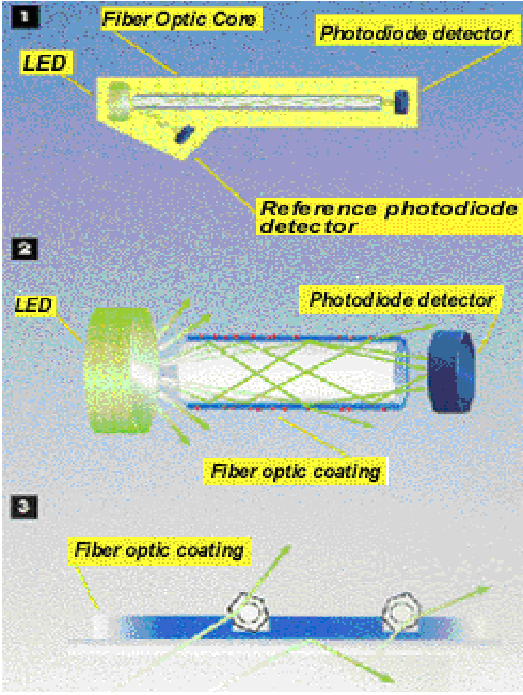
Many of the commercially developed intrinsic FOCS use coating-based sensors. Optical fibers usually consist of a core and cladding, each of which has a different refractive index. In a FOCS, a portion of the cladding is replaced by a proprietary coating that selectively and reversibly adsorbs the target organic analytes while repelling water. The interaction between the target organic analytes and the coating changes the refractive index of the coating, thereby decreasing the amount of light generated by a light emitting diode (LED) transmitting to the detector. The resultant loss of light, measured by the detector, is proportional to the concentration of organics present in the sample.
Light transmission in an optical fiber takes place by total internal reflectance. For total internal reflectance to occur, the transmitting fiber must be coated with a material with a refractive index less than that of the optical fiber material. The core of a typical glass fiber has a refractive index of 1.6, and the cladding has a refractive index of 1.5. Typical plastic fibers have a polymethacrylate core with a refractive index of 1.5 and a polymer coating with an index of 1.4.
Other measurement techniques that can be used include fluorescence, light polarization, infrared, and Raman. The type of measurement technique used by the manufacturer dictates the type of light source and detector that are used.
System Components
Components of an intrinsic FOCS consist of a light source, optical fiber, and detector. The light source typically is a LED. Another common light source is the dye laser. The optical fiber is the integral component of an intrinsic FOCS. Optical fibers are fine strands of glass or plastic that are capable of transmitting light for distances of several hundred feet. The diameter of optical fibers ranges from 0.05 microns to as large as 0.6 centimeters.
Detectors consist of photodiodes, photomultiplier tubes (PMT), and silicon charge-coupled-device (CCD) arrays. A photodiode, or silicon diode transducer, consists of a reverse-biased pn-silicon junction formed on a silicon chip. The reverse bias creates a depletion layer that reduces the conductance of the junction to nearly zero. If radiation (light) impinges the chip, holes and electrons are formed in the depletion layer and swept through the device to produce a current that is proportional to the radiant power. Silicon diodes are more sensitive than vacuum phototubes but less sensitive than photomultiplier tubes. Photodiodes have a spectral range of about 190 to 1100 nanometers.
A PMT consists of an evacuated transparent envelope called a phototube with a cathode and a wire anode sealed inside. The surface of the cathode supports a layer of photoemissive material that emits electrons when irradiated. The tube also contains additional electrodes called dynodes. Electrons emitted after irradiation from the photoemissive material on the cathode are accelerated toward the dynode. Upon striking the dynode, each photoelectron causes the emission of several electrons that are accelerated toward the next dynode. After this process has repeated nine times, 1 to 10 million electrons have formed for each incident photon. The cascade is finally collected at the anode and the resulting current is then electronically amplified and measured. PMTs are highly sensitive to ultraviolet and visible light and have extremely fast response times.
The Raman spectroscopy system also has a spectrograph for separating the return light into its wavelength components and directing them onto a detector to quantify the amount of light at each wavelength. Older devices used a PMT. While these systems are still used, they have been largely replaced by diode arrays and CCD arrays. CCDs are preferred because of their ability to measure many wavelengths at once, and because they have a large wavelength range (400-1000 nm), large dynamic range, high quantum efficiency, low read noise, and low dark noise (Lewis and Edwards 2001).Like Raman, the LIBS system requires a spectrograph to separate spark-return light into wavelength components that are quantified by a time-gated, intensified, linear detector array.
Mode of Operation
Figure 1 illustrates how an intrinsic FOCS operates. Part 1 of the figure shows the sensing element that combines a short optical fiber core with a hydrophobic/organophilic chemical coating. Light is transmitted into the optical fiber from a LED and detected at the opposite end by a photodiode detector. A reference detector monitors the LED output and compensates for light source fluctuations. The amount of light transmitted to the detector is dependent upon the difference in refractive index of the optical fiber core and the chemical coating.
How a Intrinsic FOCS Operates
When the probe is immersed into water containing VOCs, the VOCs that partition into the organophilic coating change the effective refractive index of the coating, allowing light to escape from the optical fiber. The resultant loss of light reaching the detector correlates to the concentration of VOCs present.
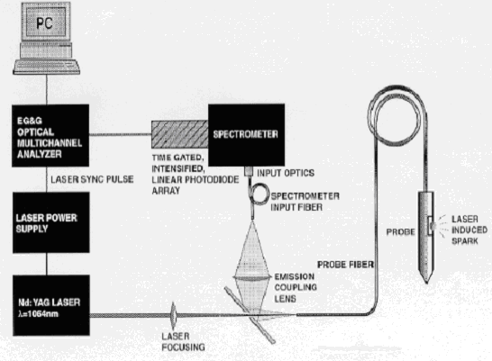
When a LIBS system is mounted on a direct push rig, a laser is directed into the fiber optic cable to the probe where it is focused by a short-focal-length quartz lens through a sapphire window and onto the soil. Because the soil is pressed against the window, the lens-to-sample distance is fixed. The focused laser light generates sufficient power to cause an induced plasma, in other words, it breaks-down a minute amount of soil into a ionized gas. Radiation (light) generated by this plasma is returned by the fiber optic cable to a coupling mirror that directs it to a spectrograph for wavelength separation. The wavelengths are sent through a gated photodiode array to a multichannel analyzer. The analyzer allows the detection of the chemical elements present in the ionized gas (plasma).
 LIBS System
In Raman spectroscopy, a laser is directed into a fiber optic cable to a probe that is exposed to the material to be sampled. A return fiber optic cable directs the inelastically scattered photons emitted by the impacted compounds back to a filter that rejects the wavelength of the incident radiation (elastically scattered photons) and reflected stray light and allows the Raman scatter to pass through. The Raman light is then separated into component wavelengths and directed to a detector.
When molecules are absorbed onto a uniformly roughened surface (generally gold, silver, or copper), they yield a Raman signal that is many times (102 to 106) more intense than normal Raman signals, and fluorescence from the analyzed species and other environmental species is quenched. Single molecules have been studied in the laboratory. This technique allows for trace analysis of organic compounds. Field deployment of surface enhanced Raman spectroscopy (SERS) usually involves a fiber optic coupled wand where the gas phase species are drawn across a metal substrate and the absorbed chemicals are pulsed with a laser. In water applications, a sample of the water can be taken and a gel or colloidal suspension placed in it. The material is queried through the walls of the container. Alternatively, a fiber optic coupled probe containing the metal substrate can be placed in the water and a measurement taken directly. SERS does not apply to direct analysis of soil samples.
Target Analytes
Intrinsic FOCS are not compound specific; they respond to classes of VOC or SVOC compounds. Extrinsic FOCs can be chemical specific. For instance, Raman is specific to metals and organic chemicals. LIBS is specific to elements and LIF is specific to monoaromatic and polycyclic aromatic hydrocarbons. The Raman and LIBS instruments are semi to fully quantitative, but generally they have ppm level detection limits. SERS is capable of ppb-level analyses.
Performance Specs
Performance specs include information on detection limits, calibration, and sample preparation.
Detection Limits
Typical detection limits for intrinsic FOCS are about 1 ppm for VOCs in water. Lower detection limits are possible with pre-concentration of the analyte. Typical detection limits for Raman spectroscopy are at the ppm level unless a surface enhanced tool is added which limits the media that can be tested to air and liquids. Detection limits for LIBS are between 0.1-200 parts per million (depending on the sample and the element of interest). LIBS achieved detection limits of 10 ppm for lead in an Environmental Security Technology Certification Program Cost and Performance Demonstration. LIF detection limits depend upon the petroleum product present and are generally in the 10s to 100s of ppm.
Calibration
Calibration involves measuring the response of the detector against a calibration standard. Calibration standards should consist of a series of known analyte concentrations in a representative sample matrix. Detector response is plotted against analyte concentration to generate a calibration curve.
As with most modern instrumentation, calibration and data acquisition is controlled and recorded with a microprocessor.
Sample Preparation
Both intrinsic and extrinsic FOCS are typically used for in situ measurements precluding sample preparation.
Advantages
- The design of FOCS provides in situ and real-time monitoring.
- FOCS are small in size due to small fiber optic diameters.
- Optical fibers are flexible within limits allowing greater access to difficult locations.
- Transmission over long distances allows monitoring in deep wells and provides a measure of safety for monitoring hazardous atmospheres.
- Multi-element analysis by intrinsic FOCS is possible using various fibers and a single central unit.
- Portable Raman spectroscopy probes can be used to determine the concentration of PCBs in oil.
- A LIBS probe mounted on a direct push platform can investigate heavy metal contamination at depth.
Limitations
- Many intrinsic FOCS are not compound-specific, react to many VOCs, and produce readings only for the concentration of total VOCs. The detection limits can be high compared with conventional analytical methods, such as gas chromatography.
- FOCS are mainly used to detect gross contamination.
- Some sensors are temperature and time dependent. A temperature sensor can be added to the probe containing the intrinsic FOCS to compensate for changes in temperature. Because sensor response is based on diffusion, the measured concentration may vary with the amount of time the intrinsic FOCS is in contact with the target analyte. Therefore, it is critical that equilibrium be achieved before a measurement is taken. Most intrinsic FOCS reach equilibrium in 5 to 10 minutes, which is indicated by a steady state signal.
- The number of reversible reactions (adsorption and subsequent desorption), is limited, so intrinsic probes may have to be regenerated after extended use.
- Because dynamic ranges are usually lower for intrinsic FOCs than for traditional electrodes, either the sample must be diluted or the sensor recalibrated.
Cost Data
FOCS costs vary significantly. Instrument design and accessories affect instrument prices.
Verification/Evaluation Reports
Verification of the performance of site characterization and field analytical technologies is conducted through a variety of programs. Evaluation and verification reports from EPA's Superfund Innovative Technologies Evaluation (SITE) Measuring and Monitoring Program, EPA's Environmental Technology Verification Program (ETV) program, and the Department of Defense's (DOD's) Environmental Security Technology Certification Program are provided below.
Superfund Innovative Technologies Evaluation (SITE) Measuring and Monitoring Program
The SITE Demonstration Program encourages the development and implementation of innovative treatment technologies for remediation of hazardous waste sites and for monitoring and measurement. In the SITE Demonstration Program, the technology is field-tested on hazardous waste materials. Engineering and cost data are gathered on the innovative technologies so that potential users can assess the technology's applicability to a particular site. Data collected during the field demonstration are used to assess the performance of the technology, the potential need for pre- and post-treatment processing of the waste, applicable types of wastes and waste matrices, potential operating problems, and approximate capital and operating costs. The following reports from the measuring and monitoring program are available for fiber optic chemical sensors:
- Innovative Technology Evaluation Report: Site Characterization Analysis Penetrometer System (SCAPS), EPA/540/R-95/520, August 1995 http://www.epa.gov/esd/cmb/site/pdf/papers/sb125.pdf
- Innovative Technology Evaluation Report: Rapid Optical ScreenTool (ROST™), EPA/540/R-95/515, August 1995 http://www.epa.gov/esd/cmb/site/pdf/papers/sb131.pdf
EPA's Environmental Technology Verification (ETV) Program
EPA's Environmental Technology Verification (ETV) Program verifies the performance of innovative technologies. ETV was created to substantially accelerate the entrance of new environmental technologies into the domestic and international marketplaces. ETV verifies commercialized, private sector technologies. After the technology has been tested, the companies receive a verification report that they can use in marketing their products. The results of the testing also are available on the Internet. The following reports from the ETV program are available for fiber optic chemical sensors:
- Laser Induced Fluorescence Sensors http://www.epa.gov/etv/verifications/vcenter1-10.html
DoD's Environmental Security Technology Certification Program
The goal of DoD's Environmental Security Technology Certification Program is to demonstrate and validate promising, innovative technologies that target the DoD's most urgent environmental needs. These technologies provide a return on investment through cost savings and improved efficiency. Technologies that have been certified through this program are listed below. Links are provided to the web sites that provide the Certified Environmental Technology Transfer Advisory and the Certification Notice for the technologies.
- Cost and Performance Report: POL Sensor Validation of SCAPS
March 1997 (CU-9517)
https://serdp-estcp.mil/projects/details/b19baa84-c00e-4be5-a1ce-da210d467e9e
Final Report: Fiber Optic Biosensors for Contaminant Monitoring
Environmental Security Technology Certification Program ESTCP Project Number CU-0115, 79 pp 2005
Cost and Performance Report: Site Characterization and Analysis Penetrometer System (SCAPS) Heavy Metal Sensors
Environmental Security Technology Certification Program ESTCP Project Number CU-9716, 45 pp. 2003
Site Characterization and Analysis Penetrometer System (SCAPS) Heavy Metal Sensors Demonstration/Validation Technology Demonstration Report
Lieberman, S. and P. A. Boss
Environmental Security Technology Certification Program, Report Number 1868, 114 pp, 2001
References
Lewis, I. and H. Edwards. 2001. Handbook of Raman Spectroscopy: From the Research Laboratory to the Process Line. Marcel Dekker, New York, NY.
